Design Manual for Roads and Bridges


Highway Structures & Bridges
Design
CD 358 Waterproofing and surfacing of concrete bridge decks
(formerly BD 47/99, BA 47/99 & IAN 96/07)
Version 2.4.0
Summary
This document gives the requirements for the design, materials and workmanship for the waterproofing and surfacing of concrete bridge decks.
Application by Overseeing Organisations
Any specific requirements for Overseeing Organisations alternative or supplementary to those given in this document are given in National Application Annexes to this document.
Feedback and Enquiries
Users of this document are encouraged to raise any enquiries and/or provide feedback on the content and usage of this document to the dedicated National Highways team. The email address for all enquiries and feedback is: Standards_Enquiries@highwaysengland.co.uk.
This is a controlled document.Latest release notes
| Document Code | Version number | Date of publication of relevant change | Changes made to | Type of change |
|---|---|---|---|---|
| CD 358 | 2.4.0 | March 2022 | Core document, Scotland NAA | Incremental change to requirements |
| Publication of Scotland National Application Annex to CD 358. For historic information, please note there are no versions 2.1.0 or 2.2.0 of this document due to a software error. Version 2.0.0 was published in June 2020 and then replaced by version 2.3.0 in February 2022. | ||||
Previous versions
| Document Code | Version number | Date of publication of relevant change | Changes made to | Type of change |
|---|---|---|---|---|
| CD 358 | 2.3.0 | February 2022 | Core document | Incremental change to requirements |
| CD 358 | 2.0.0 | June 2020 | ||
| CD 358 | 1.0.0 | March 2020 | ||
| CD 358 | 0.0.0 | July 2019 |
Foreword
Publishing information
This document is published by National Highways.
This document supersedes BD 47/99, BA 47/99 and IAN 96/07, which are withdrawn.
Contractual and legal considerations
This document forms part of the works specification. It does not purport to include all the necessary provisions of a contract. Users are responsible for applying all appropriate documents applicable to their contract.
Introduction
Background
The risk of deterioration of concrete decks due to mechanisms such as freeze-thaw damage and chloride-induced corrosion of reinforcement is strongly influenced by contact with water and deicing salts. Effective water management in the form of adequate drainage and the application of waterproofing to the upper surface of the deck have an important role in controlling this risk.
Such waterproofing has to be sufficiently robust to resist transient vehicular loading, maintain good adhesion to the deck and the surfacing, be resistant to deicing salts and possess long-term durability.
Waterproofing is designed to be installed across the full extent of the upper surface of the deck after it has been properly prepared and reached a suitable moisture content. The lapping of new waterproofing onto existing waterproofing is to be avoided due to the high risk of failure.
Ventilating layers and additional protective layers (APL) (particularly in conjunction with thinner surfacing and incorrect temperature during laying) have been a source of premature failure and measures to overcome this are detailed within this document.
Assumptions made in the preparation of the document
The assumptions made in GG 101 [Ref 16.N] apply to this document.
Mutual recognition
Where there is a requirement in this document for compliance with any part of a “British Standard” or other technical specification, that requirement may be met by compliance with the Mutual Recognition clause in GG 101 [Ref 16.N].
Abbreviations
| Abbreviation | Definition |
|---|---|
| APL | Additional protective layer |
| COSHH | Control of substances hazardous to health |
| NDT | Non-destructive testing |
| PAS | Product acceptance scheme |
| PWS | Permitted waterproofing system |
| TAA | Technical approval authority |
Terms and definitions
| Term | Definition |
|---|---|
| Additional protective layer | bituminous material laid on specified areas of the complete waterproofing system to protect it from damage during construction, surfacing and resurfacing operations |
| Certification body | a body accredited in accordance with BS EN 45011 or BS EN ISO/IEC 17065 by the United Kingdom Accreditation Service (UKAS) or equivalent European accreditation organisation, which is party to a multi-lateral agreement (MLA) with UKAS or any equivalent International Accreditation Forum (IAF) MLA signatory with a scope that includes the relevant standard(s) |
| Permitted waterproofing system | waterproofing system that meets the requirements set out within Appendix A |
| Protective layer | material, such as a board, forming part of a permitted waterproofing system laid on the waterproofing membrane to protect it from damage during construction |
| Sub-surface drainage | system for draining water from within the surfacing |
| Surfacing | road, footway, central reserve and verge wearing surface course or combination of wearing surface course and base binder course |
1. Scope
Aspects covered
1.1 This document sets out the requirements for waterproofing and surfacing concrete decks of highway bridges, including accommodation bridges, tunnels, box-type underpasses, culverts and cattle creeps. It shall apply to new waterproofing works and, where appropriate, to the maintenance and repair of existing waterproofing works.
1.2 This document shall not be used for waterproofing other parts of bridge structures (such as below ground surfaces, piers and abutments and other salt spray-susceptible areas).
1.3 This document shall not be used for waterproofing footbridges, steel decks and aqueducts.
NOTE This document contains the design performance and certification requirements for use of waterproofing systems.
1.4 Where the bottom slab of tunnels and box-type underpasses carries traffic, and where a ground slab is used in a traffic underpass, the slab carrying traffic shall be waterproofed and surfaced as a bridge deck.
1.5 Where the top of an aqueduct is over-slabbed and carries a highway, the top slab shall be considered as a bridge deck.
1.6 The top slabs of concrete buried structures shall be waterproofed in accordance with the requirements of this document.
1.7 Where the construction technique, such as thrust boring, means the external faces are inaccessible for the application of waterproofing, proposals for mitigating the risk of water ingress shall be submitted to the TAA of the Overseeing Organisation for approval as part of the CG 300 [Ref 27.N] technical approval process.
Implementation
1.8 This document shall be implemented forthwith on all schemes involving waterproofing and surfacing concrete bridge decks of highway bridges, including accommodation bridges, tunnels, box-type underpasses, culverts and cattle creeps, on the Overseeing Organisations’ motorway and all-purpose trunk roads according to the implementation requirements of GG 101 [Ref 16.N].
Use of GG 101
1.9 The requirements contained in GG 101 [Ref 16.N] shall be followed in respect of activities covered by this document.
2. Drainage and water management
Water management
2.1 Bridges and highways shall be designed to prevent the accumulation of water and allow for surface water on concrete bridge decks to be effectively managed and removed through the:
- application of waterproofing to the upper surface of the deck; and,
- provision and use of appropriate drainage systems.
2.2 The design of drainage systems for the management of water from the highway shall be in accordance with the drainage requirements including CG 501 [Ref 6.N], LA 113 [Ref 25.N], and CG 502 [Ref 28.N].
Surface water drainage
2.3 Surface water shall be removed from the bridge deck by the provision of falls to suitable drainage inlets.
2.3.1 Longitudinal gradients should be a minimum of 1 in 100.
NOTE Where 1-in-100 longitudinal carriageway falls are not feasible then proposals need to be agreed through the technical approval process.
2.4 Drainage inlets shall be designed to intercept surface water and positioned adjacent to the deck joints.
2.5 The proposed carriageway topology and drainage provisions shall be designed to ensure that standing water and/or winter icing is avoided.
2.5.1 The design of the surface water management of the carriageway should include the following aspects:
- longitudinal falls;
- transverse falls (identify where crossfalls reverse on the structure);
- location, spacing and type of drainage provisions on and off the structure (edge of carriageway, subsurface drainage and substructure drainage);
- type and position of deck expansion joints; and,
- maintenance requirements for the drainage system to ensure continued functionality.
2.6 Where the requirements for drainage and water management are not possible to achieve for existing bridge decks, detailed alternative proposals shall be submitted to the Overseeing Organisation through the technical approval process.
Sub-surface drainage
2.7 Where the geometry of the deck or deck movement joints impedes water from draining naturally through surface drainage, sub-surface drainage shall be provided at at locations where water can accumulate.
2.7.1 Horizontal perforated tubes, vertical pipe drains, or other means may be provided at the level of the waterproofing system.
2.8 Where pipe drains are used, these shall be a minimum of 40 mm internal diameter to avoid blockage.
2.9 Edge drains shall be provided to drain the full depth of water-permeable surface courses:
- at the low points of the deck; and,
- where the flow of sub-surface water through the surface course is impeded, such as at expansion joints that are not the buried type.
2.10 The position of the outlets of sub-surface drainage pipes shall be such that any discharge, including formation of icicles, will not harm other parts of the structure or provide a hazard to any road user group.
2.11 Where water is likely to be trapped at a deck movement joint, such as on a low section of deck, the guidance in CD 357 [Ref 5.N] shall be followed to address this situation.
Service bays
2.12 Service bays shall have provision for drainage.
2.13 A 40 mm minimum internal diameter of pipe drains shall be used within service bays.
2.14 The position of drainage outlets in service bays shall be such that any discharge, including formation of icicles, will not harm other parts of the structure or provide a hazard to road users.
2.15 Service bays shall be left unfilled.
2.16 If a statutory undertaker requires a filling to be used within a service bay, it shall be a free draining material, such as no-fines concrete.
2.17 Where surface or sub-surface water flows towards a bridge from the approaches, suitable upstands and drainage outlets shall be provided to prevent water entering the service bays and leaking into expansion joints.
Make-up material for footways, central reserves and verges
2.18 Make-up material of either no-fines concrete or other free-draining materials or concrete shall be used over the waterproofing in footways, central reserves and verges on a concrete bridge deck.
2.18.1 Where loose filling is required in footways, central reserves and verges, it should be a material such as 10-mm nominal single size aggregate.
2.19 Sand shall not be used as a loose filling in footways, central reserves and verges.
2.20 Drainage shall be provided for removal of sub-surface water in footways, central reserves and verges.
Drainage systems
2.21 Systems for the drainage of water from bridges shall be detailed so that water is not allowed to fall freely from the bridge deck.
2.22 Closed drainage systems with facilities for rodding and other maintenance shall be provided for the drainage of water from bridges.
2.23 Drainage systems shall be sufficiently robust to withstand damage during cleaning, and resist all commonly occurring chemical spillages.
2.24 Drainage systems shall not contain details that are integral with structural elements.
2.25 Drainage waters from bridge decks shall not discharge into the drainage layers behind abutments or anywhere where the build up is likely to cause a threat to the stability of the highway or asset.
3. Detailing of bridge deck waterproofing
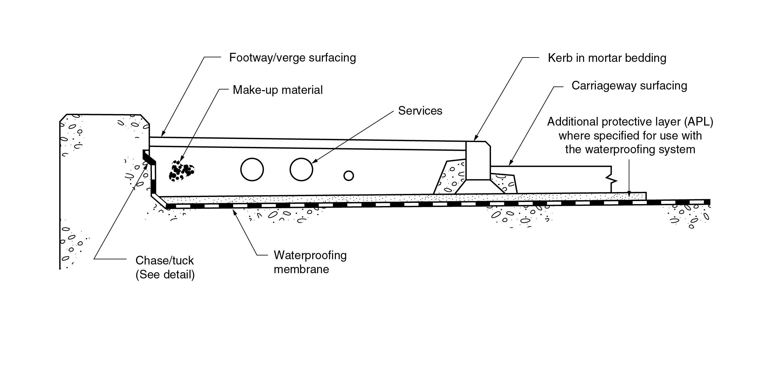
3.1 Bridge deck waterproofing shall be continuous and cover the entire deck between parapet upstands including footways, central reserves, verges, service bays and under kerbs.
3.2 Typical details of waterproofing systems on concrete bridge decks shall be in accordance with:
- Figure 3.2a; or,
- the manufacturer details provided for the product.
NOTE Further information on detailing of bridge decks is given in CIRIA R155 [Ref 3.I] and CIRIA C543 [Ref 2.I].
3.2.1 When existing waterproofing is replaced, it should be complete rather than partial replacement (see Appendix D for exceptional circumstances).
3.3 The waterproofing system shall provide a watertight seal at edges and around interruptions, such as gullies.
NOTE Some waterproofing systems can have standard details for achieving a watertight seal around some features.
3.4 The deck detailing shall be designed to assist in ensuring the effectiveness of the waterproofing.
3.5 Detailing shall enable the use of either prefabricated or liquid-applied systems and ensure continuity of waterproofing throughout, including central footways, central reserves, verges, service bays and under kerbs.
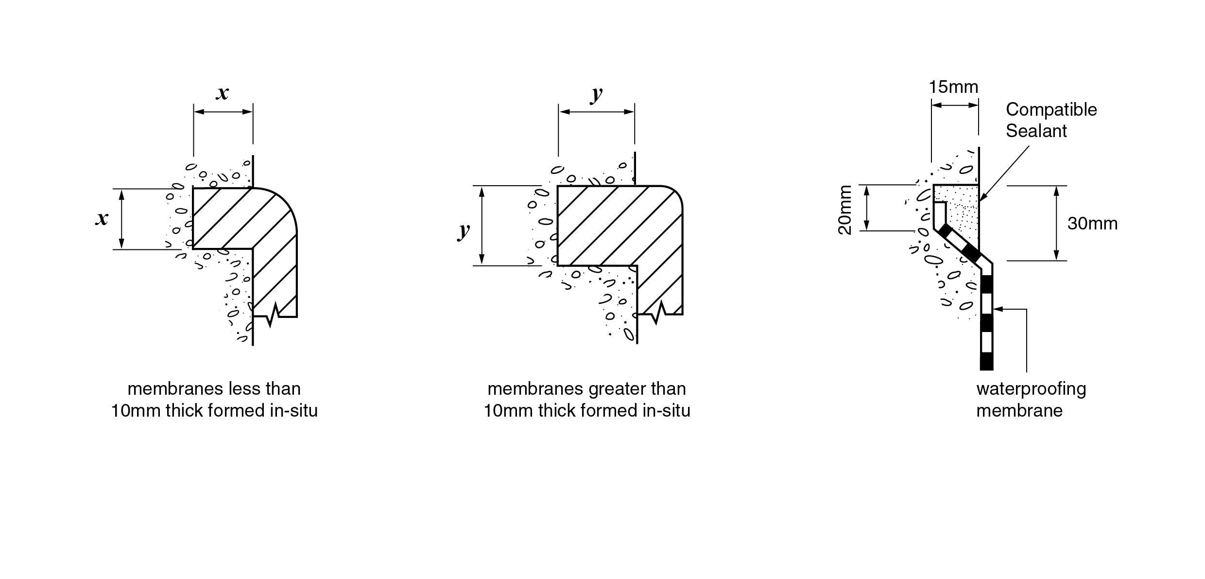
3.6 Sharp arrises and internal angles shall be avoided in the deck surface to be waterproofed.
3.7 Arrises shall be chamfered or rounded and fillets formed in internal angles.
3.8 Chases into which the prefabricated waterproofing membranes are tucked shall have the lower face splayed in accordance with Figure 3.2b.
Deck movement joints
3.9 At all movement joints in the deck, the waterproofing shall be detailed in such a way to prevent water percolating beneath the waterproofing membrane.
3.10 At sealed joints, the waterproofing membrane, the relevant parts of the joint and any sealing material shall form a continuous impervious barrier.
3.10.1 Impervious materials such as epoxy resin mortar may be bonded directly to the deck.
3.11 The detailing of waterproofing at deck movement joints including buried joints shall be in accordance with CD 357 [Ref 5.N].
NOTE If a joint is made of impervious material, waterproofing is not required underneath it.
Service bays
3.12 Service bays shall be waterproofed on all sides and the floor.
3.13 The waterproofing system for service bays shall be the same as the system used for the deck, unless otherwise agreed with the Overseeing Organisation.
Top slabs of buried structures
3.14 Where the structure is covered with fill, such as in the case of underpasses, culverts and cattle creeps, a waterproofing system shall be specified for the buried top slab in accordance with this document unless otherwise agreed with the Overseeing Organisation.
3.15 Where the top slab of the buried structure is continuous with the abutments, waterproofing on the top surface shall be continued down the outside of the abutment to a level 200 mm below the soffit.
4. Concrete deck construction
Surface finish
4.1 The finish to unformed surfaces of new or existing bridge decks, and top slabs of buried structures receiving waterproofing, shall be specified as Class U4 in accordance with MCHW Series 1700 [Ref 17.N].
4.2 Where a new or existing concrete surface for waterproofing does not meet Class U4, repair work shall be undertaken to achieve this class.
4.3 Concrete repair materials shall be specified in accordance with CS 462 [Ref 24.N] and be compatible with the waterproofing system and deck concrete (similar strength, coefficient of thermal expansion and elastic modulus).
5. Waterproofing systems
5.1 The waterproofing systems specified for installation on concrete bridge decks and buried top slabs constructed, improved, or maintained in accordance with MCHW Series 2000 [Ref 18.N] shall be a PWS complying with:
- BS EN 14695 [Ref 9.N] for sheet applied systems;
- ETAG 033 [Ref 15.N] for liquid applied systems; or,
- PAS in MCHW Series 0100 [Ref 19.N].
NOTE 1 Procedures to enable the use of waterproofing systems in highway contracts are given in Appendix A.
NOTE 2 Test requirements for the certification of waterproofing systems for concrete bridge decks are given in Appendix B.
NOTE 3 Procedures and requirements for certification site trials are given in Appendix C.
NOTE 4 Procedures for lapping onto existing waterproofing systems are given in Appendix D.
5.2 A PWS shall have a valid and current certification at the time of use.
5.3 The waterproofing systems specified for use on concrete bridge decks and buried top slabs shall have an assumed intended minimum working life of 25 years.
5.4 The waterproofing system specified for use on concrete bridge decks and buried top slabs shall be compatible with the concrete and the concrete surfacing.
5.5 Project specific trials shall be required where the concrete has been impregnated or received treatment that might reduce the bond.
5.6 As-built, operational and maintenance records of the waterproofing system shall be provided in accordance with the requirements in CG 302 [Ref 2.N].
6. Installation and workmanship
General
6.1 Waterproofing systems shall be installed in accordance with the manufacturer's specified procedures.
Bond of waterproofing system
6.2 The adhesion and bond achieved for a waterproofing system shall be consistent with that expected for the system.
6.3 The adhesion and bond at all interfaces of the waterproofing system shall be uniform in order ensure the durability of the concrete deck, waterproofing system and surfacing.
6.4 The waterproofing system shall be capable of consistently attaining the minimum adhesion and bond values in Table 6.4.
| Test | Testing temperature | Surfacing thickness (mm) | ||
| 120 | 90 120 | 60 90 | ||
| (1) Tensile adhesion: waterproofing system to concrete | -10°C | 0.3 MPa | 0.5 MPa | 0.7 MPa |
| 23°C | 0.3 MPa | 0.5 MPa | 0.7 MPa | |
| 40°C | 0.2 MPa | 0.3 MPa | 0.3 MPa | |
| (2) Shear bond: surfacing to waterproofing system | -10°C | 0.3 MPa | 0.3 MPa | 0.4 MPa |
| 23°C | 0.3 MPa | 0.3 MPa | 0.4 MPa | |
| 40°C | 0.1 MPa | 0.15 MPa | 0.15 MPa | |
| (3) Tensile bond: surfacing to waterproofing system | 23°C | 0.4 MPa | 0.45 MPa | 0.5 MPa |
Detailing
6.5 Ventilating layers, partial bonding or bond breakers shall not be used with the waterproofing system.
6.6 All waterproofing systems shall be terminated in a chase.
6.7 Where a prefabricated membrane is terminated in a chase, the rebate shall be filled with a compatible sealant in accordance with Figure 3.2b.
6.8 Where a liquid applied membrane is terminated in a chase, the membrane shall be taken into the chase, but a sealant is not required.
Integrity of waterproofing systems
6.9 Pinholes, blowholes or blisters shall not be permitted on the waterproofing system.
6.10 Any making good shall be in accordance with the manufacturer's method statement for the system.
Sheet membrane systems
6.11 Where they occur, laps on adjacent waterproofing sheets shall be staggered.
NOTE Overlapping of multiple sheets can create a thickened area of sheeting that can form a weak spot in the bond.
Waterproofing systems applied to concrete less than 28 days old.
6.12 Waterproofing systems applied to early aged concrete (that is concrete aged 7 to 28 days), shall meet the minimum performance requirements provided in Table 6.4.
NOTE 1 A decrease in the age at which concrete is waterproofed can be beneficial as it can reduce congestion on the road network and realise cost benefits from a reduced construction programme.
NOTE 2 Research has shown that the performance of waterproofing systems is not generally adversely affected by application to concrete aged seven days or more, provided the requirements of Table 6.4 are met.
NOTE 3 The findings of the research and guidance on the application of waterproofing systems to concrete 7 to 28 days old are as follows:
- The most significant differences in the performance of a waterproofing system applied to 28-day-old and younger concrete are likely to be dependent on:
-
- the resistance to blow/pin holing and blistering of the system;
- the bond of the system to the concrete;
- the effect of the moisture content of the concrete on the curing of components of the system; and,
- shrinkage and load induced cracking.
- The performance differences in point 1 above are dependent on:
-
- the type of concrete;
- the surface finish of the concrete;
- the moisture content of the concrete when the waterproofing system is applied;
- the temperature of the concrete when the waterproofing system is applied;
- the type of the waterproofing system, in particular the type of primer; and,
- the temperature history after the waterproofing system has been applied, including the temperature of surfacing materials.
- Shrinkage and load-induced cracking can be significant in the hogged regions of continuous multi-span decks.
NOTE 4 Further information on the research and guidance on the application of waterproofing systems to young concrete (7-28 days) can be found in TRL PPR 221 [Ref 5.I] and TRL PPR 154 [Ref 1.N].
6.13 The ability of the waterproofing system to bridge cracks where it is applied on young concrete before the onset of cracking shall be specified.
NOTE A waterproofing system and its overlaying structure can be subjected to larger tensile strains if they are applied to the deck before the onset of cracking.
Lapping onto existing waterproofing systems
6.14 Lapping of a waterproofing system onto existing systems shall be agreed with the Overseeing Organisation and used in accordance with the procedures in Appendix D.
7. Protection of waterproofing
7.1 Damage to the waterproofing system shall be avoided after it has been applied and before it has been overlaid with APL (where required) or asphalt.
7.2 Any damage to the waterproofing system shall be repaired in accordance with the method statement agreed with the certification body for the system.
7.3 Waterproofing shall be protected from damage during construction through control of the construction processes and plant, and use of temporary protection in accordance with MCHW Series 2000 [Ref 18.N].
7.4 Indicator mesh or similar products shall not be used.
7.5 Temporary protection against damage during construction shall be as for decks that are to be surfaced in accordance with MCHW Series 2000 [Ref 18.N].
7.6 Permanent protection to the waterproofing of buried top slabs shall be either a bituminous APL or ST1 concrete in accordance with MCHW Series 2000 [Ref 18.N].
Additional protective layer
7.7 APL shall not be used unless it is a specific requirement of the waterproofing system.
7.8 Where required, APL shall be installed in accordance with the product manufacturer’s certification and instructions.
7.9 Installation procedures for the APL shall be clearly identified, including the temperature requirements.
7.10 A waterproofing system requiring an APL shall not be used if the thickness of the surfacing material overlaying the APL is restricted to less than 100 mm.
7.11 APL of sand asphalt shall not be laid by hand.
7.11.1 Black sand asphalt may be used as an APL in preference to asphalt with a red tint.
7.12 APL shall not exceed 20 mm nominal thickness in order to retain stability.
7.13 APL material shall not be used as a regulating course.
7.13.1 Where there is a restricted depth of surfacing, kerbs may be bedded directly onto the APL.
Service bays
7.14 Waterproofing on the floor of service bays shall receive permanent additional protection with one of the following:
- 20-mm sand asphalt protection;
- 50 mm nominal thickness of ST1 concrete to MCHW Series 2600 [Ref 21.N]; or,
- approved tiles hand set in bitumen.
8. Surfacing on carriageways
8.1 On both flexible and rigid pavement roads, the surfacing on bridge decks shall be surfaced with bituminous materials complying with MCHW Series 0900 [Ref 20.N].
NOTE A list of the permitted surfacing materials is provided in CD 236 [Ref 4.I].
8.1.1 Accommodation bridges may be treated similar to bridges on flexible or rigid pavement roads and their decks surfaced with bituminous materials or surfaced with concrete.
8.2 For new works, the designed total minimum thickness of surfacing material shall be 120 mm including the waterproofing system, any protective layer and any APL.
NOTE 1 In the past where the thickness of surfacing has been reduced for practical and/or economic reasons premature failure has occurred when the asphalt has broken up and potholes developed on the carriageway.
NOTE 2 Premature failures of the waterproofing system have been attributed to several factors, including:
- the accumulation of sub-surface water in the asphalt;
- poor bond of the asphalt layers to the waterproofing system;
- excessive thickness of the waterproofing membrane;
- low compressive modulus of the waterproofing system; and,
- low fatigue resistance of the asphalt layers..
NOTE 3 Research into premature failures has resulted in several changes including:
- emphasis on the importance of sub-surface drainage;
- strengthening bond requirements;
- specifying deformation limits for all mixtures within 100 mm of the surface; and,
- specifying maximum air void contents for all asphalt mixtures.
NOTE 4 Further information about factors that affect performance of surfacing on bridge decks and causes of premature failure can be obtained from TRL PPR 221 [Ref 5.I], TRL RR 317 [Ref 6.I] and TRL 655 [Ref 1.I].
8.3 The surfacing material laid over the waterproofing and APL (if present) shall consist of binder and surface courses.
8.3.1 On flexible pavement roads the surface course on the bridge deck should be the same as for the road on the approaches to the structure and carried through over the bridge at the same thickness.
8.3.2 Where a bridge has not been designed or retrofitted with pavement drainage, an impervious surface such as hot-rolled asphalt (HRA) should be used rather than thin surfacing course systems (TSCS).
8.4 Where the bridge deck and/or approaches are to be resurfaced, the minimum length of machine-laid surfacing shall be 15 m from any transverse vertical discontinuity in the pavement.
NOTE 1 Vertical pavement discontinuities include plug joints and metallic elements of bridge joints.
NOTE 2 Clause 946 of the MCHW Series 0900 [Ref 20.N] provides details of stepping requirements for the joints of the resurfaced area with the existing bituminous pavement.
8.5 The deformation resistance of all binder course layers (and base if applicable) overlaying the waterproofing system shall have a Class 2 deformation resistance measured using the wheel-tracking test in BS EN 12697-22 [Ref 4.N], all in accordance with MCHW Series 0900 [Ref 20.N].
8.6 The asphalt layer directly overlaying the waterproofing system shall have a design (not in situ) air-void content of no more than 4% so that the amount of sub-surface water that enters the layer is low.
NOTE A thin surface course system with a suitable bond coat will help to seal the binder course and reduce the flow of sub-surface water into the binder course(s) (and APL (if present)).
8.7 Provision shall be made to ensure good bond between the adjacent laid widths, but in a way that does not allow water to accumulate in parts of the asphalt layers.
NOTE 1 A fully sealed joint will prevent the horizontal flow of water through the asphalt layers.
NOTE 2 The vertical faces of the joints between laid widths (rips) of asphalt are usually sealed with bitumen to prevent water ingress.
8.8 The upper surface of a surface course joint shall never be coated with bitumen after it has been compacted.
8.9 Where the asphalt layer directly overlaying the waterproofing system contains coarse aggregates, the voids at the base of the asphalt layer shall be prevented from interconnecting.
8.9.1 A suitable bond coat may help to fill the voids at the base of the asphalt layer and prevent them from interconnecting.
Maintenance resurfacing on carriageways
8.10 For maintenance works, the total minimum thickness of surfacing material required shall allow for the existing circumstances.
8.11 Where reduced surfacing thickness is used, the performance of the waterproofing system shall be in accordance with the relevant requirements in Table 6.4.
8.11.1 Where the thickness of surfacing to be laid on the waterproofing system is required to be less than 120 mm (including any protective layer and APL), special surfacing material designed for thin layers may need to be used.
Temperature for laying and compacting
8.12 Contractors shall give details of:
- the minimum temperature at which the surfacing is to be laid, and by which compaction is to be essentially completed, to ensure that the bond coat of the waterproofing system is activated; and,
- how stripping of the bond coat by the paver and other vehicles is to be minimised and repaired before and during surfacing.
8.13 The asphalt directly overlaying the waterproofing system shall be laid and compacted at temperatures that are sufficiently high to:
- form a dense layer; and,
- activate the bond coat so the asphalt is uniformly and well bonded to the system.
8.14 The temperature at the level of the waterproofing system shall be measured immediately after the asphalt has been laid, and when compaction is essentially completed.
8.15 Laying and compaction temperatures shall be chosen to take into account the requirements of the bond coat to form a dense layer that is firmly bonded to the waterproofing system.
8.16 The measured temperature shall exceed the minimum temperatures required to activate the bond coat by at least 10°C.
8.17 If necessary, a site trial shall be carried out to ensure that the minimum temperatures are always achievable in both machine- and any hand-laid areas.
8.18 If recorded temperatures are below the required levels referred to in Clause 8.11, then the surfacing shall be removed and the waterproofing prepared again.
8.19 Any damage to the waterproofing system shall be repaired.
8.20 If the surfacing is to be laid and compacted at temperatures that exceed those permitted by MCHW Series 0900 [Ref 20.N] it shall be demonstrated before works commence on site that this will not damage the waterproofing system.
Bridge deck expansion joints
8.21 The surfacing thickness at deck expansion joints shall be a minimum of 120 mm including any protective layer and the waterproofing system and any APL, unless otherwise agreed with the Overseeing Organisation.
NOTE 1 The risk of failure of waterproofing and surfacing at bridge deck expansion joints is high due to the interfaces between different components.
NOTE 2 Achieving the required laying and compaction temperatures at bridge deck expansion joints can also be more difficult, especially where materials are hand laid.
Bonding of APL or surfacing to the waterproofing system
8.22 The specified bond coat shall be compatible with the APL or surfacing, and the waterproofing system.
8.23 Where a bond coat for the APL or surfacing is not required as part of the waterproofing system, the binder within the directly applied surfacing shall be capable of providing the bond required with the waterproofing system.
NOTE Minimum bond values for different thicknesses of surfacing material are given in Table 6.4.
9. Surfacing on footways, central reserves and verges
9.1 The surfaces of footways, central reserves and verges shall be laid to falls so that surface water will be shed into the drainage system.
9.1.1 Precast or stone flags should only be used as surfacing where the make-up material over the waterproofing is concrete.
NOTE The joints between precast or stone flags can develop cracks, which will admit water.
9.2 Where the make-up material is loose, filling base course shall be used before the flexible surfacing is applied.
9.2.1 The surfacing may be applied directly to a stable make-up material such as concrete or no-fines concrete.
9.3 No-fines concrete make-up material shall first be sealed with sand-cement slurry before laying mastic asphalt surfacing.
NOTE Mastic asphalt to BS 6925 [Ref 26.N] type R988 and type T1097 are unsuitable for paving.
10. Normative references
The following documents, in whole or in part, are normative references for this document and are indispensable for its application. For dated references, only the edition cited applies. For undated references, the latest edition of the referenced document (including any amendments) applies.
| Ref. | Document |
|---|---|
| Ref 1.N | TRL Limited. Calder AJJ, Evans MG, & Jordan RW. TRL PPR 154, 'Application of bridge deck waterproofing to concrete aged from 3 to 28 days' |
| Ref 2.N | National Highways. CG 302, 'As-built, operational and maintenance records for highway structures' |
| Ref 3.N | BSI. BS EN 13108-6, 'Bituminous mixtures. Material specifications. Mastic Asphalt (Designated Standard - CPR)' |
| Ref 4.N | BSI. BS EN 12697-22, 'Bituminous mixtures. Test methods for hot mix asphalt. Wheel tracking' |
| Ref 5.N | National Highways. CD 357, 'Bridge expansion joints' |
| Ref 6.N | National Highways. CG 501, 'Design of highway drainage systems' |
| Ref 7.N | EOTA. TR 022, 'Determination of the resistance to the passage of chloride ions through a waterproofing layer subjected to indentation by aggregate' |
| Ref 8.N | BSI. BS EN 1297, 'Flexible sheets for waterproofing. Bitumen, plastic and rubber sheets for roof waterproofing. Method of artificial ageing by long term exposure to the combination of UV radiation, elevated temperature and water' |
| Ref 9.N | BSI. BS EN 14695, 'Flexible sheets for waterproofing. Reinforced bitumen sheets for waterproofing of concrete bridge decks and other trafficked areas of concrete. Definitions and characteristics (Designated Standard - CPR)' |
| Ref 10.N | BSI. BS EN 13596, 'Flexible sheets for waterproofing. Waterproofing of concrete bridge decks and other concrete surfaces trafficable by vehicles. Determination of bond strength' |
| Ref 11.N | BSI. BS EN 14224, 'Flexible sheets for waterproofing. Waterproofing of concrete bridge decks and other concrete surfaces trafficable by vehicles. Determination of crack bridging ability' |
| Ref 12.N | BSI. BS EN 14694, 'Flexible sheets for waterproofing. Waterproofing of concrete bridge decks and other concrete surfaces trafficable by vehicles. Determination of resistance to dynamic water pressure after damage by pre-treatment' |
| Ref 13.N | BSI. BS EN 13653, 'Flexible sheets for waterproofing. Waterproofing of concrete bridge decks and other concrete surfaces trafficable by vehicles. Determination of shear strength' |
| Ref 14.N | BSI. BS EN 14692, 'Flexible sheets for waterproofing. Waterproofing of concrete bridge decks and other concrete surfaces trafficable by vehicles. Determination of the resistance to compaction of an asphalt layer' |
| Ref 15.N | EOTA. ETAG 033, 'Guideline for European Technical Approval of Liquid Applied Bridge Deck Waterproofing Kits' |
| Ref 16.N | National Highways. GG 101, 'Introduction to the Design Manual for Roads and Bridges' |
| Ref 17.N | Highways England. MCHW Series 1700, 'Manual of Contract Documents for Highway Works, Volume 1 Specification for Highway Works - Series 1700 Structural Concrete' |
| Ref 18.N | Highways England. MCHW Series 2000, 'Manual of Contract Documents for Highway Works, Volume 1 Specification of Highways Works, Series 2000 Waterproofing for concrete structures' |
| Ref 19.N | Highways England. MCHW Series 0100, 'Manual of Contract Documents for Highway Works. Volume 1 - Specification for Highway Works. Series 100 - Preliminaries ' |
| Ref 20.N | Highways England. MCHW Series 0900, 'Manual of Contract Documents for Highway Works. Volume 1 Specification for Highway Works. Series 900 Road Pavements – Bituminous Bound Materials.' |
| Ref 21.N | Highways England. MCHW Series 2600, 'MCHW Vol.1 'Manual of Contract Documents for Highway Works, Volume 1 Specification for Highway Works - Series 2600 Miscellaneous' |
| Ref 22.N | BSI. BS EN 13578, 'Products and systems for the protection and repair of concrete structures. Test method. Compatibility on wet concrete' |
| Ref 23.N | BSI. BS EN 1766, 'Products and systems for the protection and repair of concrete structures. Test methods. Reference concretes for testing' |
| Ref 24.N | National Highways. CS 462, 'Repair and management of deteriorated concrete highway structures' |
| Ref 25.N | National Highways. LA 113, 'Road drainage and the water environment' |
| Ref 26.N | BSI. BS 6925, 'Specification for mastic asphalt for building and civil engineering (limestone aggregate)' |
| Ref 27.N | National Highways. CG 300, 'Technical approval of highway structures' |
| Ref 28.N | National Highways. CG 502, 'The certification of drainage design' |
11. Informative references
The following documents are informative references for this document and provide supporting information.
| Ref. | Document |
|---|---|
| Ref 1.I | Transport Research Laboratory. TRL 655, 'Asphalt surfacing to bridge decks' |
| Ref 2.I | Construction Industries Research and Information Association, London. Soubry, MA. CIRIA C543, 'Bridge detailing guide' |
| Ref 3.I | Construction Industries Research and Information Association, London. Ray SS, Barr J, and Clark L. CIRIA R155, 'Design for improved buildability' |
| Ref 4.I | National Highways. CD 236, 'Surface course materials for construction' |
| Ref 5.I | Transport Research Laboratory. TRL PPR 221, 'The performance of surfacing overlaying bridge deck waterproofing systems' |
| Ref 6.I | Transport Research Laboratory. TRL RR 317, 'Waterproofing of concrete bridge decks: Site practice and failures' |
Appendix A. The use of waterproofing systems in highway contracts
Only a permitted waterproofing system (PWS) is to be specified for installation on concrete bridge decks and buried top slabs constructed, improved, or maintained in accordance with MCHW Series 2000 [Ref 18.N].
A PWS is a waterproofing system that is certificated by an appropriate certification body and falls within any of the following four categories:
- CE marked in accordance with the harmonised standard BS EN 14695 [Ref 9.N] for sheet-applied systems;
- has ETAG 033 [Ref 15.N] for liquid-applied systems;
- a historic system compliant with a PAS in MCHW Series 0100 [Ref 19.N]; or,
- not in accordance with 1) or 2) but obtains certification from a PAS in MCHW Series 0100 [Ref 19.N] through compliance with the procedures and requirements in Appendix B and Appendix C of this document.
Although systems in category 1) or 2) above are compliant products or systems, their use is subject to satisfying other specific assessments in Appendix B and/or Appendix C of this document as agreed with the Overseeing Organisation.
The specific assessments to be carried out exclude those characteristics and performance requirements that have already been verified or satisfied in accordance with BS EN 14695 [Ref 9.N] or ETAG 033 [Ref 15.N].
The main purpose of additional specific assessments for category 1) and 2) systems is to ensure that:
- acceptance of their use is as rigorous as those required for the certification of category 3) or 4) systems; and,
- they can be installed safely and perform as expected in an environment with similar conditions to those encountered on motorways and all-purpose trunk roads.
For example, a site trial is required by the Overseeing Organisation for category 1) and 2) systems. However, this could be avoided where evidence is available to demonstrate that the system has been previously used elsewhere on a bridge with installation and demand characteristics similar as those likely to be encountered on motorways and all purpose trunk roads.
The certification of a PWS is to be reviewed and updated at intervals agreed with the certification body.
Where any PWS shows itself to be unsatisfactory by failing to maintain its certified or verified performance levels, the Overseeing Organisation can suspend or remove permission for use of the system in motorways and trunk road works, notwithstanding the validity of any certification, ETAG or CE marking.
Appendix B. - Procedures for certification of waterproofing systems on concrete bridge decks
B1 Introduction
This appendix gives a series of procedures for the certification of non-CE-marked waterproofing systems for concrete bridge decks.
The Overseeing Organisation reserves the right to amend or supplement the tests required for certification.
Certification will be given only if the waterproofing system meets the requirements and successfully passes the site trial.
B2 Procedure
The procedure for certification is divided into the following stages:
- application for assessment;
- review of waterproofing system; and,
- provision of a site trial on an actual bridge deck.
The manufacturer may withdraw from the remainder of the test programme at the completion of any of these stages.
B2.1 Application for assessment
Manufacturers requiring a waterproofing system to be assessed submit the following basic details of their waterproofing system to the certification body.
B2.1.1 For all systems:
- system name;
- description of materials;
- storage requirements and shelf life;
- installation method statement;
- repair techniques;
- on site integrity testing by NDT method(s);
- expected working life; and,
- health and safety data sheets and COSHH assessments.
B2.1.2 Where applicable:
- concrete surface preparation;
- type of primer;
- type of adhesive and application temperature;
- number of layers/coats;
- type of protection;
- type of bond coat(s) for bituminous overlay(s);
- minimum activation temperature(s) of system or bond coat(s); and,
- other details.
B2.1.3 Additional details required for sheet and board systems:
- dimensions;
- weight; and,
- handling temperatures.
B2.1.4 Additional details required for liquid-applied systems:
- mixing time of components;
- pot life of mixed liquid materials;
- nominal coverage rates;
- setting time;
- cured/dry density;
- mix details; and,
- dry film minimum/maximum thickness (see procedure for 2 mm minimum thickness in Appendix C, C2.5).
B2.2 Site trial
Following the successful results of the review programme (see B3) the manufacturer or his representative then undertakes a site trial (see Appendix C).
B3 Review of waterproofing system
The review programme for the waterproofing system is sub-divided as follows:
B3.1 Identification and quality control
Identification and quality control data and certification are to be reviewed by the certification body for the purpose of checking the manufacturer's submitted data (see B2.1) against the requirements.
This initial review will not form part of the certification but the certification body will advise the manufacturer on the suitability of the submitted system for continuing with the certification procedure.
The manufacturer may withdraw at this stage.
B3.1.1 Release of dangerous substances
Certification body is to review compliance of the declaration submitted by the manufacturer in relation to relevant aspects of BS EN 14695 [Ref 9.N] Clause 4.4 or ETAG 033 [Ref 15.N] Clause 5.1.3.
B3.2 Checks and tests on waterproofing system
The submitted waterproofing system is to be checked and tested by the certification body for compliance with the performance and other requirements given in this document.
The test methods and product performance requirements are given in B4.
B3.3 Site trial checks and tests.
Prior to installation of the waterproofing system, the certification body verifies:
- the suitability and condition of the bridge deck for the site trial including any preparation necessary; and,
- the quality assurance statement of all materials forming the waterproofing system.
During the installation of the waterproofing system and the asphalt surfacing, certification body records the following as applicable:
- age of concrete;
- installation temperature of the system;
- relative humidity;
- weather conditions, including wind speed;
- nominal coverage rates;
- setting time;
- thickness applied;
- pin/blow holing/blistering;
- bond of the membrane to the concrete bridge deck;
- in situ integrity NDT method(s);
- repair procedure;
- workmanship and supervision;
- damage to system prior to asphalt surfacing;
- temperature of asphalt when laid and when compaction essentially completed;
- damage caused by asphalt surfacing; and,
- bond of the asphalt surfacing to the system.
B4 Test methods and performance requirements
For all tests where the temperatures are (-10±2)°C, (+23±2)°C, and (40±2)°C respectively the relative humidity (RH) at +23°C is to be (50±5)% and the actual RH at the other temperatures recorded.
B4.1 Tests on unbonded sheets, boards and film of liquid applied membranes (where applicable)
B4.1.1 Dimensional checks
- straightness of sheets; the straightness of sheets is in accordance with BS EN 14695 [Ref 9.N] Clause 4.2.2;
- width of sheets; width of sheets is in accordance with BS EN 14695 [Ref 9.N] Clause 4.2.2; and,
- thickness;
-
- the thickness of sheets is in accordance with BS EN 14695 [Ref 9.N] Clause 4.2.2.; and,
- for sheet and board samples submitted for examination and testing, the thickness measured at any location is to be within ±10% of the intended nominal thickness.
B4.1.2 Mass per unit area
The mass per unit area of sheets is in accordance with BS EN 14695 [Ref 9.N] Clause 4.2.2.
The mass per unit area of liquid applied membranes is declared in accordance with ETAG 033 [Ref 15.N] Clause 5.1.7.2.4.
B4.1.3 Water absorption
The water absorption of sheets is determined in accordance with BS EN 14695 [Ref 9.N] Clause 4.2.5.
The water absorption of cured liquid-applied membranes is determined in accordance with ETAG 033 [Ref 15.N] Clause 6.1.7.1.2.1.
The increase in weight cannot exceed 7%.
Specimens which exceed this limit are subjected to freezing for 24 hours at (-10±2)°C.
After the freeze period the specimens are conditioned for at least four hours at (23±2)°C and then observed under a minimum of x20 magnification for damage or thickness change.
When compared with a control specimen there is no damage and for sheets and boards, any change in thickness is limited to ±10% of the control thickness.
B4.1.4 Resistance to water penetration
The resistance to water penetration of sheets is in accordance with Clause 4.3.8. of BS EN 14695 [Ref 9.N] and for liquid-applied systems in accordance with ETAG 033 [Ref 15.N] Clause 6.1.1.8.
The testing of both sheets and liquid applied membranes is to include specimens with the limiting overlap specified by the manufacturer of the system, and where appropriate, butt joints.
No water penetration can be observed after 28 days.
B4.1.5 Resistance to chisel impact
Liquid-applied membrane specimens are prepared and tested for impact resistance in accordance with Clause 5.1.1.4.3 of ETAG 033 [Ref 15.N] and then chloride-ion penetration tests applied on specimens.
The chloride-ion tests are carried out in accordance with ETAG 033 [Ref 15.N] Clause 5.1.1.3.
The test is repeated on a further three specimens if any one of the three samples initially tested indicates an unacceptable increase in chloride ion concentration or significantly high solution volume loss. All the samples tested are required to pass the test.
B4.1.6 Resistance to aggregate indentation
The resistance of sheet systems to aggregate indentation is determined in accordance with BS EN 14695 [Ref 9.N] Clause 4.3.6.
A ‘resistant’ result is required for visual inspection and for watertightness to BS EN 14692 [Ref 14.N], using Method 2.
The resistance of cured liquid applied membranes to aggregate indentation is determined in accordance with ETAG 033 [Ref 15.N] Clause 5.1.1.4.1.
Test results are also required for watertightness and resistance to perforation in accordance with ETAG 033 [Ref 15.N] Clause 5.1.1.8 and Clause 5.1.1.6 respectively.
B4.1.7 Resistance to dynamic water pressure
The resistance to dynamic water pressure of sheet systems and liquid-applied membranes after damage by pretreatment is to be assessed in accordance with BS EN 14694 [Ref 12.N]. The test is repeated on testing on separate samples at (-10±2)°C and (40±2)°C.
B4.2 Tests on waterproofing systems bonded to concrete
B4.2.1 Application to concrete with high moisture content or young concrete
Unless the manufacturer restricts the requirement for the application of the waterproofing system to the age of concrete substrates of a minimum of 28 days, the procedures in this sub-section apply.
For young concrete (7 to 28 days old) the tests are carried out on concrete substrate cured to BS EN 1766 [Ref 23.N] for seven days.
The ability to apply liquid-applied waterproofing system to the concrete substrate with high moisture content or young concrete is established in accordance with ETAG 033 [Ref 15.N] Clause 5.1.7.2.6.1.
For sheet waterproofing systems the bond strength is determined in accordance with BS EN 14695 [Ref 9.N] Clause 4.3.2.
Immediately prior to the application of the waterproofing system, the concrete can be either wet (with the surfaces to be coated being dabbed with an absorbent paper towel, after BS EN 13578 [Ref 22.N]Clause 7.3(a), or be surface-dried in accordance with the manufacturer’s normal site procedure.
The waterproofing membrane is bonded to the concrete between 7 and 9 days old.
The effects of thermal shock are simulated using the method given in ETAG 033 [Ref 15.N] Clause 5.1.1.5(i) with hot sand, and Type 1 specimens, within three days of applying the waterproofing system.
The manufacturer of the waterproofing system specifies the maximum temperature and type of bituminous mixtures that can be laid on the system in service.
The maximum temperature applies during the thermal shock and it is not less than 170°C.
The bond strength of the waterproofing system to the concrete substrate is determined within five days of applying the waterproofing system.
The bond strength to the support is assessed at the testing temperatures in Table 6.4 (Test 1) with two tests at each temperature.
The tensile adhesion at failure for the interface between the waterproofing system and the concrete for each individual sample is not less than the value shown in Table 6.4 (Test 1).
B4.2.2 Tensile adhesion test
The bond of sheets to the concrete substrate is determined in accordance with BS EN 14695 [Ref 9.N] Clause 4.3.2.
The bond of cured liquid-applied membranes to the concrete substrate is determined in accordance with ETAG 033 [Ref 15.N] Clause 5.1.1.1.
If the manufacturer’s range for the concrete temperature at which the system can be applied lies outside the range 5°C to 35°C, the waterproofing system is fully bonded to concrete base specimens while they are maintained at the declared minimum and/or maximum temperature ±2°C, in combination with maximum relative humidity ± 5% allowed by the manufacturer’s installation instructions for its product.
The bond strength to the support is assessed at three temperatures.
The tensile adhesion at failure for the interface between the waterproofing system and the concrete for each individual sample is not less than the value shown in Table 6.4 (Test 1).
B4.2.3 Resistance to chloride-ion penetration
The resistance to chloride penetration of sheet and liquid-applied systems are determined in accordance with TR 022 [Ref 7.N].
The requirements for chloride-ion penetration is met when, after 28 days:
- the maximum increase in chloride ion is not more than 0.04%;
- the maximum loss in volume of liquid in the test vessel is less than 20 ml;
- there is no deterioration or debonding of the membrane from the substrate;
- there is no inter-laminar salt penetration; and,
- there is no significant surface sweating.
B4.2.4 Resistance to freeze-thaw
The resistance to freeze-thaw of sheet systems is determined in accordance with ETAG 033 [Ref 15.N] Clause 5.1.7.1.3.2(a).
The resistance to freeze-thaw of cured liquid-applied membranes is determined in accordance with ETAG 033 [Ref 15.N] Clause 5.1.7.1.3.2(a).
Following freeze-thaw cycling, three specimens are assessed for bond stress.
Three specimens are assessed for chloride-ion penetration.
The bond strength to the support is assessed at three temperatures as follows:
1. the bond of sheet systems and liquid-applied membranes to the concrete substrate is determined in accordance with BS EN 13596 [Ref 10.N];
2. the tensile adhesion at failure for the interface between the waterproofing system and the concrete for each individual sample is not less than the value shown in Table 6.4 (Test 1); and,
3. the three other samples are subjected to the chloride-ion test (B4.2.4) at (23±2)°C, after completion of the freeze-thaw cycling, and conditioned for at least 24 hours at (23±2)°C.
B4.2.5 Thermal shock and heat ageing on bond
The effects of thermal shock are simulated using the method given in ETAG 033 [Ref 15.N] Clause 5.1.1.5(i) with hot sand, and Type 1 specimens.
The manufacturer of the waterproofing system specifies the maximum temperature and type of bituminous mixtures that can be laid on the system in service.
This temperature applies during the thermal shock and it is not less than 170°C.
Heat ageing is then applied to the Type 1 sheet system and liquid-applied membrane specimens which have been subject to thermal shock.
The heat ageing is applied in accordance with ETAG 033 [Ref 15.N] Clause 5.1.7.1.3.1(a).
Following heat ageing the bond strength to the support is assessed at two temperatures as follows:
1. The bond of sheet systems and liquid-applied membranes to the concrete substrate is determined in accordance with BS EN 13596 [Ref 10.N]; and,
2. The tensile adhesion at failure for the interface between the waterproofing system and the concrete for each individual sample are not less than the value shown in Table 6.4 (Test 1).
B4.2.6 Thermal shock, heat ageing and crack cycling
The effects of thermal shock on sheet systems and cured liquid-applied membranes are assessed in accordance with ETAG 033 [Ref 15.N] Clause 6.1.1.5, as follows:
- base specimens are (400 ±5) mm ×(200 ±2) mm × ≥ 40 mm in accordance with BS EN 14224 [Ref 11.N] Clause 4.3.2;
- the effects of thermal shock are assessed using the method given in ETAG 033 [Ref 15.N] Clause 5.1.1.5(i) with hot sand, and Type 1 specimens. The manufacturer of the waterproofing system specifies the maximum temperature and type of bituminous mixtures that can be laid on the system in service; and,
- this temperature applies during the thermal shock and it is not less than 170°C.
Heat ageing is carried out in accordance with ETAG 033 [Ref 15.N] Clause 5.1.7.1.3.1(a).
The capacity to bridge cracks after thermal shock and heat ageing are determined in accordance with ETAG 033 [Ref 15.N] Clause 6.1.1.2 and Clause 5.1.1.2 (A), with Type 1 specimens, using the procedure given in BS EN 14224 [Ref 11.N].
The crack cycling temperature is no higher than (‑10 ±2)°C.
B4.2.7 Asphalt to waterproofing system interface shear adhesion test
The shear strength of sheet systems are determined in accordance with BS EN 14695 [Ref 9.N] Clause 4.3.3.
The shear strength of cured liquid-applied membranes are determined in accordance with BS EN 13653 [Ref 13.N] as referred to by ETAG 033 [Ref 15.N] Clause 5.1.4.2, in conjunction with ETAG 033 [Ref 15.N] Clause 5.1.1.7, noting that the relevant failure strength could relate to slippage between the waterproofing layer and the concrete support, slippage within the waterproofing layer, or slippage between the asphalt and the waterproofing layer.
This test is conducted at (-10±2)°C, (23±2)°C and (40±2)°C respectively. Fifteen size (A) concrete blocks, that is five blocks for each test temperature, are used with the system fully bonded together with any bond coat specified for the system.
The test samples are preconditioned at (-10±2)°C, (23±2)°C and (40±2)°C for at least four hours.
The shear bond stress at failure for the interface between the surfacing and waterproofing system for each individual sample is not less than the value shown in Table 6.4 (Test 2).
B4.2.8 Asphalt-to-waterproofing system interface tensile bond test
The asphalt-to-waterproofing system bond strength of sheet systems are determined in accordance with BS EN 14695 [Ref 9.N] Clause 4.3.2, using a Type 3 specimen to BS EN 13596 [Ref 10.N] Clause 4.3.
The asphalt-to-waterproofing system bond strength of cured liquid-applied membranes is determined in accordance with ETAG 033 [Ref 15.N] Clause 5.1.4.1.
Tensile bond stress at failure for the interface between the waterproofing system and the sand asphalt or hot rolled asphalt are not less than the value shown in Table 6.4 (Test 3).
B4.3 Site trial
Procedures and requirements for the site trial are given in Appendix C.
The site trial is formally assessed by the certification body.
The Overseeing Organisation reserves the right to attend any site trial.
Appendix C. Procedures for site trials
Part of the procedure for establishing a PWS that is compliant with a PAS and MCHW Series 0100 [Ref 19.N], is a successful site trial on an actual bridge deck.
This can only take place only after the laboratory tests and checks have been successfully completed by the certification body for waterproofing systems that are non-CE-marked in accordance with BS EN 14695 [Ref 9.N] or ETAG 033 [Ref 15.N], and have a declaration of performance that complies with the requirements specified in this document.
It is then for the manufacturer or his representative to arrange for the system to be installed on a bridge the Overseeing Organisation considers suitable for the trial.
In arranging the site trial, the manufacturer or his representative takes into account the following procedures.
C1 Preliminary requirements
C1.1 Handling requirements
The following handling procedure are undertaken before proceeding with the site trial.
C1.1.1 Rolls of sheet membranes
- Complying with the manufacturer's storage conditions, rolls of sheet membranes are conditioned at (-10±2)°C, (23±2)°C and (40±2)°C respectively for 24 hours.
- The manufacturer may declare a reduced temperature range for handling, but this includes 4°C to 30°C and the range limits are tested and assessed.
- The membranes are then unrolled immediately on removal from conditioning.
- The following procedures apply:
-
- no edge damage to roll during conditioning;
- one-man operation to unroll;
- minimal increase in stiffness of the sheet;
- membrane lays flat without damage or rucking;
- no cracking in the membrane on unrolling;
- recoil not to exceed 2.5 m over a length of 10 m;
- edge curl not to exceed a height of 50 mm in 150 mm; and,
- deviation from the straight edge is limited to that specified in BS EN 14695 [Ref 9.N] Clause 4.2.2.
C1.1.2 Unrolling sheet membranes from a mandrel
- Three longitudinal and three transverse specimens (450 ±50) mm are cut from the roll, wound onto a 25 mm diameter mandrel and secured with tape.
- These are then conditioned at (-10±2)°C, (23±2)°C and (40±2)°C respectively for 24 hours.
- The manufacturer may declare a reduced temperature range for handling but this includes 4°C to 30°C, and the range limits are assessed.
- The membranes are then unwound slowly at the stored temperature:
-
- One end is bent through 90° and the other end is tapped gently to a 90° corner; and,
- The ease of cutting is checked using a razor-edged knife.
- The following procedures apply:
-
- a minimal increase in the stiffness with no embrittlement;
- no damage, cracking, permanent set or dimensional instability;
- membrane easily cut to shape with minimal contamination of cutting blade; and,
- good resistance to tearing under normal handling.
C1.1.3 Board materials
- Specimens and sizes are prepared similarly to those for unrolling sheet membranes from a mandrel but laid flat under the same temperature conditions.
- The flexibility, damage and tendency for dimensional instability are checked as above.
- The tear and ease of cutting are checked for boards as above.
C2 Procedures for waterproofing systems bonded to concrete
The following procedures are undertaken before proceeding with the site trial.
C2.1 Resistance to pin/blow holing (principally liquid-applied membranes)
Four size (B) 300 x 300 x 55 mm concrete blocks are used for this assessment.
Unless the manufacturer restricts the requirement for the application of the waterproofing system to the age of concrete substrates of a minimum of 28 days, the waterproofing membrane is bonded to concrete base specimens of between 7-9 days old, and the test is then carried out within five days.
Two size (B) of these blocks are immersed in water for a minimum of 24 hours, removed and the surface allowed to dry in still air for up to two hours at (23±2)°C.
The sealer/primer and waterproofing membrane is applied according to the manufacturer’s requirements to all four blocks as one or two coats.
The samples are observed after two hours for pin/blow holes or blisters.
Temperature and relative humidity should be recorded during the test.
There should be no blisters and not more than four pin/blow holes continuous or non-continuous within a central area of 250 x 250mm for both samples.
The size of any pin/blow hole present is recorded and no pin/blow hole should exceed 1 mm in diameter.
The procedure for pin/blow holing applies to single-coat, two-coat or more-than-two-coat membranes.
Where single-coat membranes do not comply with the above procedures, the manufacturer is given the opportunity of applying the membrane as two or more coats to the same total thickness.
If then acceptable, the system is used as a two-coat or more-than-two-coat membrane and the remainder of the tests assessment are as for a two-coat or more-than-two-coat membrane.
C2.2 Setting of a liquid-applied membrane on a concrete block with a high moisture content
During the pin/blow holing assessment, the setting time of the membrane on the four blocks is also noted.
The nominal value for the membrane on the wetted blocks is within ±10% of the average setting time on the dry blocks, unless the manufacturer specifies differently.
If the manufacturer specifies differently, then the time accords with the manufacturer's declared limits.
C2.3 Nominal coverage rates of all liquid components of the system
During preparation of the samples, nominal coverage rates will be confirmed by the manufacturer or its representative.
C2.4 Joints
The following tests are undertaken to ascertain the performance of joints.
C2.4.1 Day joints
This test is carried out to determine whether an adequate bond can be achieved between two layers of the waterproofing membrane, applied one over the other, within a short period of time to simulate day joints.
The bond strength is to be determined in accordance with ETAG 033 [Ref 15.N] Clause 5.1.1.1 or BS EN 14695 [Ref 9.N] except that the test specimen includes a second waterproofing layer applied between 24 hours and 48 hours of the application of the first layer and include any pre-treatment required by the manufacturer.
C2.4.2 Section joints
This test is carried out to determine whether acceptable adhesion can be achieved between two layers of the waterproofing membrane applied one over the other between seven days and six months of the application of the first layer.
The test simulates section joints that may occur between waterproofing different sections of a bridge or where patch repairs may be required.
The bond strength between two layers of membranes is determined by preparing specimens in accordance with the procedures referred to in B4.2.2.
After curing for seven days at 23 °C, the specimen is exposed to UV radiation, elevated temperature and water according to BS EN 1297 [Ref 8.N] for 7 days.
After the exposure, a second waterproofing layer is applied according to the instructions of the manufacturer.
Following the curing time specified by the manufacturer, the bond strength between the two layers of waterproofing is determined in accordance with B4.2.2 and complies with the requirements of B4.2.2.
C2.5 Site trial
Where a bridge is being considered for the site trial, the bridge owner or highway authority considers the importance of the bridge location (that is, not on a strategic route), when giving agreement in principle to the installation of a waterproofing system undergoing a certification site trial.
The certification body is sent a general arrangement drawing of the bridge showing the size and type of deck including a cross-section showing details of the waterproofing system.
A minimum deck area of 150 m2 is necessary, and the bridge includes some features such as parapet upstands, service bays, chases and fillets.
Also required are details of:
- bridge name, location and bridge owner/highway authority;
- whether the bridge is of new construction or in the course of maintenance;
- surfacing type, thickness, and size and type of aggregate when not given on the drawing;
- additional protective layer, (that is sand asphalt) to be applied to the system, if applicable;
- make-up of deck concrete, that is proportion of cement replacements and other additives in the concrete;
- concrete curing method; and,
- proposed dates of installation of the system and surfacing (when this is not known then the likely dates, which can be confirmed as the programme progresses).
Where the certification body confirms that the bridge is acceptable for the site trial, the manufacturer or its representative can pursue arrangements with the highway authority and the contractor, and advise them that the site trial will be formally assessed by the certification body.
The Overseeing Organisation reserves the right to attend the site trial.
The site trial is performed in a workman-like manner by trained operatives under competent supervision and affords the level of quality of workmanship required for the certification.
In addition to the PAS requirements, the works comply with MCHW Series 2000 [Ref 18.N] .
The site trial includes observation of the preparation of the concrete deck, the installation of the waterproofing system and the surfacing.
The performance of the system between its installation and prior to overlaying with the surfacing is also monitored.
On arrival at the trial site the certification body inspects the condition of the concrete deck.
The deck is U4 finish in accordance with MCHW Series 1700 [Ref 17.N] but the manufacturer or his representative may opt to apply the system on a deck with a lesser finish in consultation with the certification body.
Where the deck has a lesser finish, the system will be expected to perform as though the finish was U4.
The deck surface is clean, dry and free from ice, frost and laitance as stated in MCHW Series 2000 [Ref 18.N].
Before any part of the waterproofing system is installed, the certification body verifies that the system has the specific characteristics in the declaration of performance and complies with the requirements specified in this document.
Discrepancies that arise with respect to either site conditions or changes to the waterproofing system are agreed with the certification body before the site trial can proceed.
On site, the concrete surface and air temperature are measured by the manufacturer or his representative using thermocouples or similar.
The concrete surface and air temperature are checked frequently over the period of the site trial.
The relative humidity is also noted at the same time.
The nominal coverage rates and setting times of the liquid components of the system accord with the manufacturer's specification.
Checks are made for ponding of primers and that any ponding that has occurred is minimal.
During and after installation of the system the following procedures apply:
- the hot bitumen adhesives for sheet systems are not greater than 240°C measured using a suitable temperature probe by the manufacturer or its representative;
- the thickness of liquid membranes is a minimum of 2 mm over peaks, arrises and irregularities in the concrete deck;
- the thickness of liquid membrane is checked with a wet-film thickness gauge or other appropriate method by the manufacture or their representative;
- there is an appropriate bond to the concrete substrate checked by the manufacturer or his representative and it is virtually free from visible defects including pin/blow holes and blisters which are made good by repair before being covered;
- sheet and board systems are laid to follow the contours of the deck surface and are free from ripples and rucks;
- laps in sheet systems comply with Series 2000 of MCHW Series 2000 [Ref 18.N] and butt joints in board systems are formed in accordance with the manufacturer's instructions;
- the manufacturer or its representative laying the waterproofing system at the site trial demonstrate to the certification body an acceptable repair method; and,
- the manufacturer or its representative demonstrate the integrity of the waterproofing membrane, including at section joints and laps, by an appropriate NDT method agreed with the certification body.
The waterproofing system is checked for damage before applying the APL (if applicable) or the asphalt surfacing.
Where damage has occurred, it is suitably repaired before the trial proceeds.
In order to dispense with the requirement of the APL for waterproofing systems which are less than 20 mm thick, for which the APL is not an integral part of the manufacturer’s system, and which have complied with the aggregate indentation requirements (B4.1.5), the following procedures 1 to 12 apply, except that the APL is replaced with asphalt surfacing:
- the placing temperature of the asphalt surfacing, measured with a suitable temperature probe by the manufacturer or their representative does not exceed 145°C;
- the minimum rolling temperature of the asphalt surfacing is not less than that specified in BS EN 13108-6 [Ref 3.N] or less than the minimum declared activation temperature for bond to the system, whichever is greater;
- prior to the completion of the asphalt surfacing laying on site, the compacted but still hot asphalt surfacing is removed from a sample area of the system and any damage to the waterproofing membrane is observed;
- if damage has occurred restrictions on any further application of the surfacing may be imposed and the damaged waterproofing membrane is repaired or replaced;
- where no damage occurs the cut back areas are then filled with new replacement asphalt surfacing and compacted;
- throughout the site trial, workmanship, supervision and general site procedure will be observed by the certification body;
- where this workmanship, supervision or general site procedure is at an unacceptably low standard, certification is not granted;
- where the system is deemed to have failed the site trial, the contractor is instructed to remove the failed system from the bridge and dispose off-site;
- the bridge is then waterproofed with a registered system;
- if during the site trial it is considered that the system is unlikely to proceed to a successful conclusion, then the manufacturer or its representative may be given an opportunity to abort the site trial and propose modifications to the system/procedures to be considered for a further trial;
- the manufacturer or its representative provides a written report to the certification body with proposed changes that would overcome identified deficiencies in the original submission; and,
- if the proposed modifications are acceptable to the certification body, the manufacturer or his representative will be allowed to make arrangements for a further site trial.
Notwithstanding 1 to 12 above, the bridge owner/highway authority reserves the right to have the bridge waterproofed with a registered system.
Appendix D. Lapping onto existing waterproofing systems
Where the full replacement of an existing waterproofing system is impractical, any use of lapping onto existing waterproofing systems is subject to very thorough justification due to the increased risk of failure.
Pull-off tests on the existing waterproofing system are undertaken before breakout of concrete in order to identify any significant difference in bond strength compared to the proposed waterproofing before carrying out repairs to, or partially replacing, existing waterproofing systems.
D1 When the level of adhesion is similar (consent not required)
If the adhesion is of similar magnitude to the proposed waterproofing system, then the joint and overlap is to be in accordance with the method statement agreed with the certification body.
The minimum overlap is specified by the waterproofing contractor.
D2 When the level of adhesion is significantly different (consent required)
Where the adhesion is significantly different (>20%), the procedures below are used, subject to the agreement of the Overseeing Organisation.
Lapping onto existing waterproofing systems is only:
- used as a temporary solution (not exceeding two years duration) before a more durable permanent solution is made; and,
- in place for over six months with the formal agreement of the project manager.
A record is made of the benefits/risks and consultations with relevant parties on the acceptability of the potential maintenance liability.
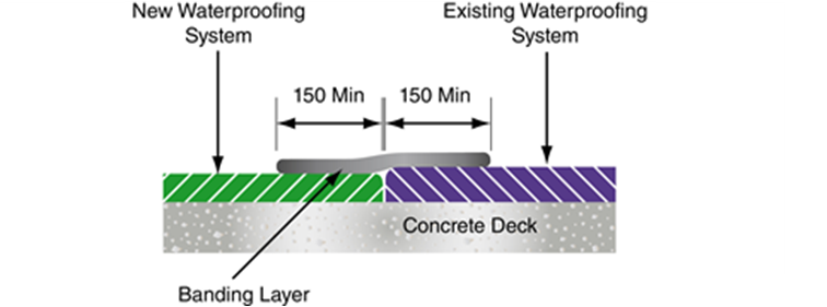
The new certified waterproofing system is butted up to the existing waterproofing system.
A protective banding layer is provided that laps a minimum of 150 mm on to both the new and existing waterproofing systems as shown below (Figure D.1).
Where there is a significant difference in thickness between the new and existing waterproofing systems, a 45° chamfer is formed in the existing system, as shown below (Figure D.2), to facilitate the lapping of the protective banding layer.
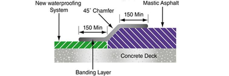
If this chamfer cannot be formed in the existing system due to either break-up of the existing system or poor adhesion to the deck, it is formed in concrete (or other similar approved material).
The presence of a concrete chamfer is recorded on both the as-built record drawings and the Overseeing Organisation's bridge management information system.