Design Manual for Roads and Bridges


Control & Communications Technology
Design
TD 131 Roadside technology and communications
(formerly TD 17/85, TD 45/17, TD 71/16, TD 72/17, TD 73/16)
Version 0.1.0
Summary
This document contains design requirements for roadside technology and communications.
Feedback and Enquiries
Users of this document are encouraged to raise any enquiries and/or provide feedback on the content and usage of this document to the dedicated National Highways team. The online feedback form for all enquiries and feedback can be accessed at: www.standardsforhighways.co.uk/feedback.
This is a controlled document.Latest release notes
| Document Code | Version number | Date of publication of relevant change | Changes made to | Type of change |
|---|---|---|---|---|
| TD 131 | 0.1.0 | November 2023 | Core document | Incremental change to requirements |
| (Version 0.1.0; Publication: Nov. 2023) This update to TD 131 includes editorial and technical changes throughout; new clauses for the provision of CCTV and ERT; and updates to the stopped vehicle detection (SVD) requirements. | ||||
Previous versions
| Document Code | Version number | Date of publication of relevant change | Changes made to | Type of change |
|---|---|---|---|---|
| TD 131 | 0 | January 2020 |
Foreword
Publishing information
This document is published by National Highways.
This document supersedes TD 17/85, TD 45/17, TD 71/16, TD 72/17 and TD 73/16, which are withdrawn.
This document incorporates roadside technology and communications content from IAN 161/15.
Contractual and legal considerations
This document forms part of the works specification. It does not purport to include all the necessary provisions of a contract. Users are responsible for applying all appropriate documents applicable to their contract.
Introduction
Background
This document contains design requirements for roadside technology and communications.
Assumptions made in the preparation of this document
The assumptions made in GG 101 [Ref 3.N] apply to this document.
Where the design of the roadside technology and communications equipment has additional testing requirements (such as contract specific requirements), it is assumed that those requirements are to be recorded in the works information.
Where this document contains design requirements, they are to be read in conjunction with the general requirements in GG 101 [Ref 3.N], GG 102 [Ref 6.N], GG 104 [Ref 9.N] and with all other DMRB documents relevant to the design of the particular works to be undertaken.
The production of infrastructure designs is to be consistent with the requirements of BS ISO 19650 - part 1 to part 3, Building Information Modelling (BIM) .
Requirements for the positioning of variable message signs and signals are described in CD 146 [Ref 5.N].
Abbreviations
| Abbreviation | Definition |
|---|---|
| ALM | Ambient light monitor |
| APTR | All purpose trunk road |
| CCD | Cross carriageway duct |
| CCTV | Closed-circuit television |
| DNO | Distribution network operator |
| DSR | Design strategy record |
| DTS | Ducts through structures |
| EI | Electricity interface |
| ERT | Emergency roadside telephone |
| GSM | Global system for mobile communications |
| MIDAS | Motorway incident detection and automatic signalling |
| NSSH | New short section of hard shoulder |
| OO | Overseeing Organisation |
| PRS | Place of relative safety |
| SDP | Service delivery point |
| STI | Service type instance |
| SVD | Stopped vehicle detection |
| TSP | Telecommunications service provider |
| VMSL | Variable mandatory speed limits |
Terms and definitions
| Term | Definitions |
|---|---|
| Chamber | In this document, a chamber is an access point to transmission, power or other cable networks. Chambers on the drainage network are not considered in this document. |
| CCTV coverage | The ability of operators and other road users to view particular parts of the highway or network |
| Communications | Transmission system to roadside technology and between local links. NOTE: This can include cable or wireless technology. |
| Connector road | A collective term for interchange links, link roads, slip roads and loops designed as part of a full grade separated junction NOTE: Definition taken from CD 122 [Ref 2.N] |
| Cross carriageway ducts (CCD) | Duct crossing a slip road or mainline carriageway, installed underneath the road surface |
| Datum point | Defined points at merges and diverges used for the purposes of locating features such as signs and signals and measuring weaving lengths NOTE: Definition taken from CD 122 [Ref 2.N]. |
| Delineated stopping bay markings | Markings within an emergency area to advise drivers where to position their vehicle |
| Ducts over gantries | Ducts over gantries comprise of both the buried ducts between chambers and a gantry base and the above ground ducts routed up and over the gantry, with access points at ground level to facilitate the pulling of cables. |
| Downstream | That part of the carriageway(s) where the traffic is flowing away from the section in question NOTE: Definition taken from CD 122 [Ref 2.N]. |
| Duct | Ducts, sub-ducts or conduits used for installing the highway communications cable network comprising communications, power and other cables |
| Ducts through structures (DTS) | Any duct installed within any structure, including:
|
| Electricity interface (EI) | Interface point between the distribution network operator (DNO) supply and the electricity network cables to road network |
Emergency area (EA) |
A purpose built place of relative safety which is located adjacent to the nearside of a mainline carriageway or diverge connector road. NOTE: The legislative title for an emergency area is an emergency refuge area and the regulations governing the use of a normal hard shoulder apply. |
| Expressway | A high speed dual carriageway that has at least two lanes in each direction, grade separated junctions, and uses technology to support operational regimes NOTE: Definition taken from GD 300 [Ref 8.N] |
| Flexible duct | Ducts of a construction that are designed to be coiled to a small radius. |
| General surveillance | An operational function that describes a network overview, with the purpose of monitoring traffic conditions, infrastructure, weather, or network performance during normal operating conditions. |
| Global system for mobile communications (GSM) | The globally accepted term for mobile cellular services covering all generations of networks. |
| Hardened verge | Areas of verge where a duct is under a hard surface; for instance a hard pavement or shallow encasement in concrete. This applies where there are location-specific space restrictions, such as retained cutting or where access pathways are provided. |
| Highway boundary | Edge of the land owned or managed by the highway authority. |
| Incident management system | The overseeing organisation system, electronic or otherwise, used for recording incident details occurring on the strategic road network. |
| Inter-junction | The region between junctions on the mainline carriageway between the merge tip of the nose of one junction and the diverge tip of the nose of the next junction. |
| Intra-junction | The section of mainline within a junction, between a diverge and merge. NOTE: Definition taken from CD 122 [Ref 2.N]. |
| Link road | In the context of junctions, a link road is a one way connector road adjacent to but separate from the mainline carriageway carrying traffic in the same direction. It is used to connect the mainline carriageway to the local highway network where successive direct connections cannot be provided to an adequate standard because the junction spacing is too close. NOTE: Definition taken from CD 122 [Ref 2.N]. |
| Local duct | Duct connecting individual roadside technology equipment to the longitudinal communications or power networks. |
| Longitudinal duct | Duct running along the length of the road to facilitate cables for the transmission telecommunications service |
| Motorway incorporating variable mandatory speed limits | All forms of motorway which have variable mandatory speed limits, including those with a hard shoulder and where the hard shoulder has been converted into a running lane, either permanently or dynamically operated. NOTE: In England this is also termed as Smart Motorway. |
| New short section of hard shoulder (NSSH) | A purpose built place of relative safety which is located adjacent to the nearside of a diverge connector road |
| Normal operating conditions | Operation of the road or technology when no severe weather or traffic incidents are occurring. |
| Nose | A paved area, approximately triangular in shape, between a connector road and the mainline at a merge or diverge, suitably marked to discourage drivers from crossing it NOTE: Definition taken from CD 122 [Ref 2.N]. |
| Off-grid energy source | Alternative energy sources, not provided by the DNO from the National Grid e.g. solar or wind power. |
| Place of relative safety (PRS) | A place (or facility) where customers can stop in an emergency. Only the following are considered as places of relative safety:
|
| Primary | Primary sites (e.g. for detectors) are the first to be located when designing a scheme. When the primary sites have been identified, other sites can be located in relation to the primary sites in accordance with spacing requirements. |
| Protected highway | As defined by SROH [Ref 10.N], Section 62 notices |
| Regional operations centre | The regional operations centre provides a regional focus for management and operation of the motorway and all purpose trunk road network. |
| Roadside technology equipment | Any equipment installed at the side, any connected, video or data device or associated component installed above, or under the carriageway of a motorway or all purpose trunk road (APTR) that provides or enables technology services. |
| Service availability | A measure of what proportion of time users have a network connection in a 90 day period, that ensures a 90 second call is completed without interruption. |
| Service delivery point (SDP) | The logical and physical location of the interface between the service type instance and the roadside technology, application or system NOTE: A number of STIs can be served by a single SDP. |
| Service type instance (STI) | A telecommunications service with defined transmission characteristics and associated performance requirements |
| Shared power supply | Where the Overseeing Organisation provides power for the telecommunications service provider (TSP) equipment NOTE: This does not allow for sharing of power supplies between roadside technology and lighting systems. |
| Slip road | A connector road between a mainline carriageway and another road NOTE 1: At the end of a slip road, traffic usually encounters a priority junction, a roundabout or traffic signals. NOTE 2: Definition taken from CD 122 [Ref 2.N]. |
| Stopped vehicle | One or more vehicles which have stopped as part of a single event on a mainline running lane or within an emergency area NOTE: A stopped vehicle excludes queuing vehicles which have stopped due to congestion or an incident. |
| Stopped vehicle detection (SVD) coverage area | All mainline carriageway running lanes to the outside of the edge markings; all mainline emergency areas and mainline sections of hard shoulder which meet the definition of a place of relative safety. NOTE: An NSSH is situated on a diverge connector road so is not included within SVD coverage area. |
| Telecommunications service | A set of information transfer capabilities delivered by a telecommunications service provider according to an agreed set of technical specifications and performance levels |
| Telecommunications Service Provider (TSP) | The TSP provides a ‘service capability’ for conveying voice, video and data signals that link roadside devices to control rooms and onto third party operational stakeholders. NOTE: The third party contracted to provide telecommunications services directly to the Overseeing Organisation. |
| Transmission cabinet | Used to house the TSP’s transmission equipment. It is a weatherproof and environmentally controlled cabinet that accommodates a variety of equipment, including termination frames, a power distribution unit, air conditioning, standby power provision in the form of batteries and a generator socket. |
| Upstream | That part of the carriageway(s) where traffic is flowing towards the section in question NOTE: Definition taken from CD 122 [Ref 2.N]. |
| Vehicle classification | The process by which the type of vehicle being detected is placed in category. Vehicles can be classified by their dimensions (length, width and height), weight, axle load, number of axles, number of wheels and their load or purpose. Subsequently, they can be compared with a list of vehicle categories. For example motorcycles, cars, buses and lorries are in different categories. Vehicle classes can also be further categorised by technical features such as weight, axle weight, height, length, width and load. |
1. Scope
Aspects covered
1.1 This document provides requirements that shall be followed for the design and implementation of roadside technology and communications on motorways and all purpose trunk roads (APTR).
NOTE This document does not describe:
- cameras used for traffic or safety enforcement;
- ramp metering infrastructure;
- variable message sign (VMS) positioning requirements;
- the performance specifications for roadside technology equipment; and,
- the provision of power supplies from Distribution Network Operators (DNO) to the electricity interface (EI) cabinet.
1.2 This document provides the design requirements for electrical power provision that shall be followed for connections commencing from the EI cabinet.
1.3 This document shall be used for the design of detection systems for traffic, stopped vehicles, or vehicle classification.
Implementation
1.4 This document shall be implemented forthwith on all schemes involving roadside technology and communication on the Overseeing Organisations' motorway and the all-purpose trunk roads according to the implementations of GG 101 [Ref 3.N].
Use of GG 101
1.5 The requirements contained in GG 101 [Ref 3.N] shall be followed in respect of activities covered by this document.
2. General
Legislative
2.1 All electrical design must comply with The Electricity at Work Regulations UKSI 1989/635 [Ref 12.N].
2.2 All electrical design shall comply with Requirements for Electrical Installations, IET Wiring Regulations BS 7671 [Ref 7.N].
Security
2.3 Potential physical security threats to the roadside technology and communications equipment shall be assessed, documented, mitigated and managed in accordance with the Overseeing Organisation's security procedure.
NOTE Examples of physical security threats to roadside technology and communications equipment can include compromised roadside equipment and metal theft.
2.4 Risks to existing roadside technology and communications equipment created by the introduction of new roadside technology and communications equipment shall be mitigated.
Design strategy record
2.5 When applying the requirements of this document, a design strategy record (DSR) shall be developed as part of the design process.
2.6 The DSR shall record departures from standard, key design decisions and constraints and assessments in support of any relaxations to requirements.
Configuration data
2.7 The site data requirements for roadside technology and communications equipment shall be established early enough in the design life cycle for any changes to be deployed.
Design for maintenance
2.8 The electrical supply isolation system shall be designed so that when an item of roadside technology equipment is isolated, those responsible for maintenance are not exposed to hazards from associated equipment, for example infra-red radiation.
2.9 Where noise fences or environmental barriers are installed between a cabinet and the carriageway, access to the cabinet shall be provided so that an effective noise or environmental barrier is maintained.
NOTE For motorways, access to the cabinet from the carriageway is from a vehicle parked on the hard shoulder or at a suitable refuge that allows maintenance vehicles to park clear of the carriageway. For APTRs, laybys can be used for parking.
2.10 Pathways between maintenance access points and cabinets shall be continuous with areas of hard standing.
2.11 Access points to gantries for cable installation shall be at ground level and facilitate the pulling of cables without the need for any access equipment.
2.12 The Overseeing Organisation's approval shall be sought for the acceptance of roadside technology equipment into maintenance and operation.
Functionality of roadside technology equipment
2.13 The required functionality of roadside technology equipment shall be determined from the operational requirements.
NOTE Roadside technology equipment needs to meet the local operational requirements that are established during early stages of the design lifecycle.
2.14 The internal operating conditions of roadside equipment cabinets shall not be adversely affected by the internal equipment layout.
Siting of roadside technology equipment
2.15 The co-location of cabinets, roadside technology equipment and end devices (such as ERT) shall be implemented, where design allows, to minimise whole life costs.
2.16 Any cabinets that are at risk from flooding shall be positioned above the flood level, determined to the requirements of CG 502 [Ref 11.N].
3. CCTV
CCTV provision
3.1 CCTV shall be provided on motorways and APTRs to meet the operational requirements of the Overseeing Organisation.
NOTE 1 Operational requirements includes maintenance and calibration of ramp metering equipment, which requires visibility of the equipment.
NOTE 2 The operational benefits of CCTV can be maximised by combining with variable message signs to provide prompt information to drivers and thus reduce the frequency of secondary accidents.
3.1.1 CCTV for general surveillance should be provided in the locations detailed in Table 3.1.1.
| Traffic volume | Coverage required |
| Traffic flow exceeds an overall average of 10,000 vehicles per lane per day on an existing motorway, or is forecast to exceed this level within the 15 year high growth estimate for a new motorway. | Motorway/motorway interchanges or motorway/major all-purpose road interchanges where there is a traffic diversion strategy or where speed or lane width restrictions are needed because of construction features such as sub-standard radius bends. |
| Motorway sections or interchanges with four or more running lanes per carriageway where there are converging/diverging traffic movements over a distance of less than 2 km. | |
| Elevated motorways within built-up areas. | |
| Within and on the approaches to motorway tunnels. | |
| Urban motorways with tidal flow and/or reduced width (or no) hard shoulders. | |
| Motorway interchanges or points with lane reductions where weekday congestion frequently occurs and queues then exceed 1 km. | |
| Exposed motorway bridges or at high elevations above sea level, where inclement weather conditions frequently necessitate restrictions or diversions. | |
| Exceptionally on APTRs in the vicinity of motorway junctions where the above criteria are met. | |
| Within links, maximum camera spacing of 1.5 km with each camera covering up to 750 m of motorway and a maximum gap in coverage of 200 m. | |
| Traffic flow is less than an overall average of 10,000 vehicles per lane per day on an existing motorway, or is not forecast to exceed this level within the 15 year high growth estimate for a new motorway. | Areas with an operational need for coverage, such as incident hot-spots, inclement weather, junctions, hills or lane drops and gains. |
3.1.2 The regional operations centre should be consulted regarding the proposed provision of CCTV on schemes to confirm the operational need for CCTV.
3.1.3 Incident management system logs and road traffic collision data should be used to determine incident hot-spots on existing roads.
3.2 On motorways incorporating variable mandatory speed limits (VMSL) where the hard shoulder is not used as a running lane or where it is dynamically used as a running lane, CCTV coverage shall enable:
- operators to see in excess of 95% of the total scheme area and be able to interpret the images correctly;
- view of a 1.75 m cube to represent a minimum of 5% of the image height at maximum zoom; and,
- coverage of ERT.
3.3 For motorways incorporating VMSL without a hard shoulder, CCTV coverage shall include the whole carriageway, emergency areas and maintenance hardstandings (where provided) to enable:
- operators to see the entire mainline carriageway running lanes and the full extent of emergency areas with no blind spots in all ambient lighting levels;
- view of a 1.75 m cube to represent a minimum of 5% of the image height at maximum zoom; and,
- views of ERT in emergency areas that represent a minimum of 10% of the image height.
NOTE A blind spot exists if a 1.75 m wide cube target (or the remaining visible area of this target when obscured) does not represent at least 5% of image height and width.
3.4 CCTV cameras associated with an emergency area shall include a pre-set position to view and zoom into the emergency area in addition to the home position and any other positions agreed with the Overseeing Organisation.
3.5 CCTV coverage of an ERT located at a new short section of hard shoulder or hard shoulder defined as a place of relative safety (PRS) shall represent a minimum of 10% of image height.
CCTV siting
3.6 CCTV cameras shall be located and mounted so that they provide the required coverage.
NOTE The CCTV coverage to take into account the SVD coverage area.
3.6.1 The location and mounting of CCTV cameras should take coverage, environmental conditions, image stability and whole life costs into account.
3.6.2 CCTV cameras should be co-located with other roadside technology equipment, for efficient construction and ongoing maintenance, including calibration.
4. Emergency roadside telephones
ERT provision
General
4.1 ERTs shall be provided on motorways and APTR to enable customers to communicate with control centres in the event of an emergency, breakdown or for assistance.
4.2 The provision of ERTs shall be consistent with the relevant class of road listed below:
- motorways with a hard shoulder;
- motorways without a hard shoulder or;
- all purpose trunk roads;
ERT on motorways with a hard shoulder
4.3 For motorways where the hard shoulder is not used as a running lane, ERT shall be provided in accordance with the ERT siting requirements.
ERT on motorways without a hard shoulder
4.4 For motorways without a hard shoulder or where it is dynamically used as a running lane, ERT shall only be provided at an emergency area and where siting requirements are met.
4.5 An ERT shall be provided at each emergency area, located 2 m (+/- 1 m) downstream of the delineated stopping bay markings.
4.6 An ERT shall be provided on a diverge connector road adjacent to a hard shoulder defined as a PRS, located at least 100 m downstream of the back of the diverge nose with a minimum of 50 m of hard shoulder upstream and downstream of the ERT location.
NOTE Locating an ERT downstream of the back of the diverge nose can mitigate the risk of late manoeuvres from the main carriageway.
4.7 An ERT shall be provided at the midpoint of a new short section of hard shoulder (NSSH) on a diverge connector road and be located a minimum of 100 m downstream of the back of the diverge nose at the midpoint of the NSSH.
NOTE Locating an ERT downstream of the back of the diverge nose can mitigate the risk of late manoeuvres from the main carriageway.
4.8 ERT shall be provided adjacent to an intra-junction hard shoulder defined as a PRS at least 100 m downstream of the back of the diverge nose, with a minimum of 50 m of hard shoulder upstream and downstream of the ERT location.
4.9 Intra-junction ERT shall be located such that they are not visible from the verge of an adjacent connector road.
4.9.1 Screening may be provided where an ERT could be visible from an adjacent connector road.
4.10 ERT on diverge connector roads shall be located such that they are not visible from an adjacent intra-junction verge.
4.10.1 Screening may be provided where an ERT could be visible from an adjacent intra-junction verge.
All-purpose trunk roads
4.11 ERTs provided on all all-purpose trunk roads shall be sited at a place of relative safety.
ERT siting requirements
4.12 ERT siting shall be prioritised around junctions before other considerations.
4.12.1 ERT should be sited in the following sequence:
- ERT locations on the main carriageway near junctions (before diverge and after merge connector roads);
- ERT locations near to (before and after) hard shoulder discontinuities;
- intra-junction ERT locations;
- inter-junction ERT locations;
- ERT locations on slip roads and motorway to motorway link roads.
4.13 ERT on the main carriageway near junctions shall be located in relation to the exit and entry datum points:
- between 400 m and 300 m upstream of the exit datum point; and,
- between 300 m and 400 m downstream of the entry datum point.
4.14 At sections of hard shoulder discontinuities, ERT shall be provided between 100 m and 300 m from the upstream and downstream tips of the discontinuity tapers.
4.15 When the full width hard shoulder length is between 100 m and 200 m, the ERT shall be placed at the midpoint of the length of full width hard shoulder.
4.16 Where the full width hard shoulder length is not between 100 m and 200 m, the provision of ERT along highways shall be designated in consultation with the Overseeing Organisation on a scheme-by-scheme basis.
4.17 Where full width hard shoulders are provided, ERT sites shall be located in the verge.
4.18 ERT shall be provided adjacent to an intra-junction hard shoulder at least 100 m downstream of the back of the diverge nose, with a minimum of 50 m of hard shoulder upstream and downstream of the ERT location.
4.19 Intra-junction ERT shall be located such that they are not visible from the verge of an adjacent connector road.
4.19.1 Screening may be provided where an ERT could be visible from an adjacent connector road.
ERT spacing
4.20 For motorways with up to three running lanes and a hard shoulder, ERT shall be provided at regular intervals, nominally spaced at 1,500 m +/-10%.
4.21 For motorways with four or more running lanes and a hard shoulder, ERT shall be provided at regular intervals, nominally spaced at 1,000 m +/-10%.
4.22 For motorways with climbing lanes, ERT spacing shall be consistent with the number of lanes in the link, not the number of lanes at the gradient.
4.23 Where ERT are to be provided on connector roads, they shall be provided at regular intervals, nominally spaced at 1,500 m +/-10%.
Upgrading/replacing ERT
4.24 Where existing ERT are being upgraded or replaced, the replacements shall be located within 10 m of the existing site.
4.25 Replacement ERT shall make use of existing cross carriageway ducts (CCD) by locating them no further than 10 m from a perpendicular line across the carriageway from ERT on the opposite carriageway.
Customer access to ERT
4.26 ERT shall be positioned so that they provide safe access for all customers.
NOTE Safe access for ERT can include provision of ramps, clearances and guardrails.
4.27 ERT shall be arranged so that any customer is able to see either an ERT that can be accessed without incurring any additional risks (e.g. from crossing carriageways or climbing structures), or a telephone legend on a distance delineator post (unless a concrete barrier is installed in the central reserve).
NOTE The presence of a concrete barrier in the central reserve reduces the risk of pedestrians crossing the carriageway, removing the need to locate ERT opposite each other.
Delineator posts
4.28 Distance delineator posts for ERT locations shall be placed every 100 m in the motorway verge.
4.29 Distance delineator posts shall only direct users to an ERT when there is a continuous hard shoulder between the distance delineator post and the ERT.
4.30 All delineator posts shall direct users to the nearest ERT that can be accessed safely.
NOTE Intra-junction ERTs minimise the risk of customers crossing slip roads to reach an ERT.
4.31 Existing distance delineator posts shall be reviewed as part of the scheme and replaced if information displayed is incorrect following the scheme.
4.32 When additional ERT are installed, the distance delineator post legends shall be updated.
Service provision to ERTs
4.33 The type of ERT to be installed shall use either the Overseeing Organisation's private telecommunications network or mobile operator networks.
NOTE A common term used for all mobile networks is global system for mobile communications (GSM).
4.34 The type of ERT for each location shall be determined through the appraisal of the network service present at that location, to include:
- the mobile operator network coverage and service availability, as well as the presence of the Overseeing Organisation's private telecommunications network; and
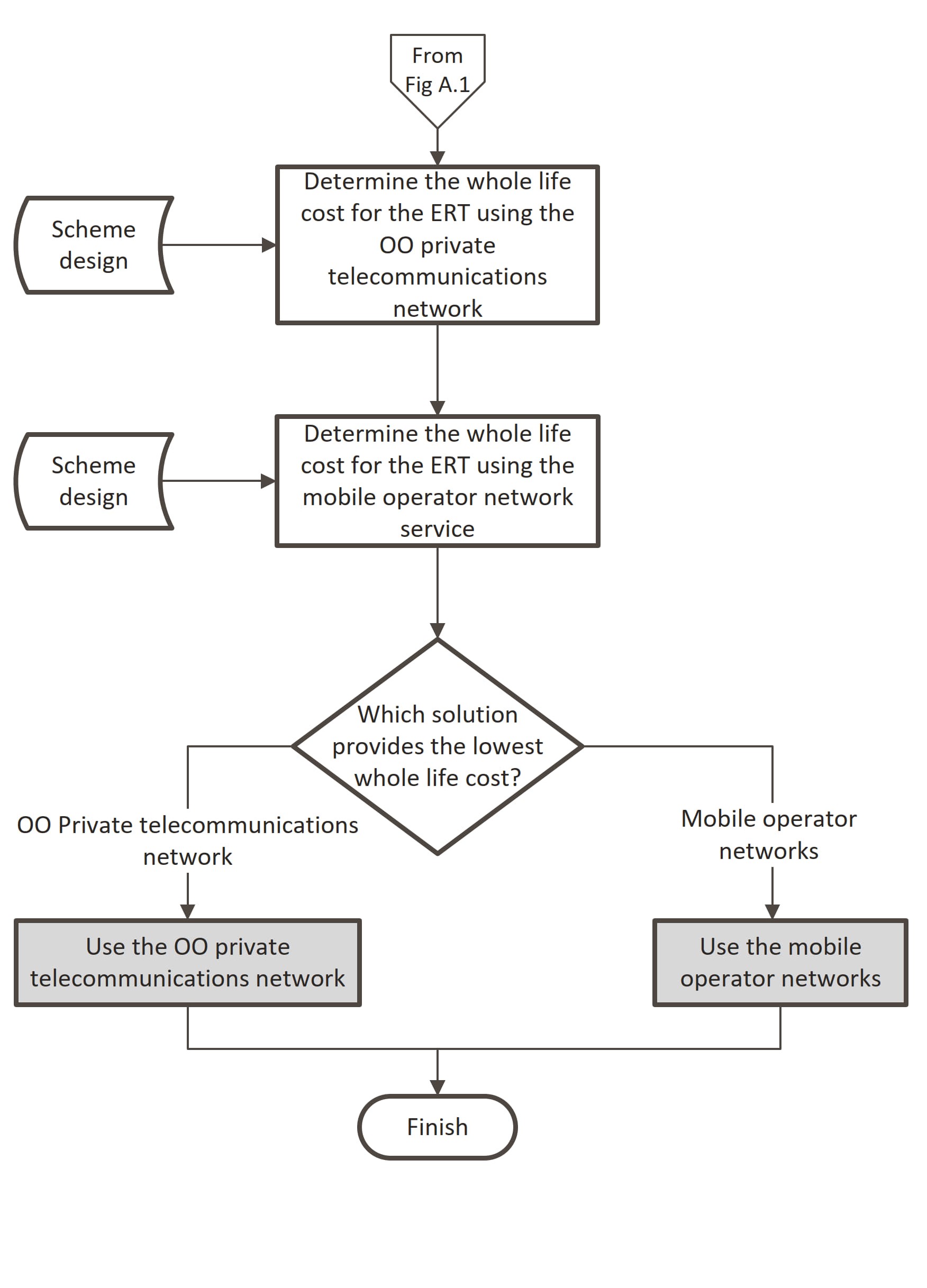
- a comparison of the whole life cost for the ERT where the network service is acceptable for both types of ERT.
NOTE 1 A method for undertaking the appraisal is provided in Appendix A.
NOTE 2 The whole life costs are not required if there is only one option that meets the network service requirements for the ERT.
4.34.1 The whole life cost of the ERT provision should take into account the Overseeing Organisation's existing telecommunications infrastructure within the scheme extents.
4.35 The results of the appraisal shall be included in the DSR.
ERTs using mobile operator networks (GSM ERTs)
4.36 The combined service availability for the proposed mobile operators that provide an acceptable signal level to support a single GSM ERT shall be at least 99.9%.
4.36.1 When the combined service availability from the proposed mobile operators that provide an acceptable signal level to support a single GSM ERT cannot be achieved, advice may be sought from the Overseeing Organisation.
NOTE The service availability for mobile operators is taken from published data and is only valid for the stated timescales. The future service availability for mobile operators cannot be guaranteed by the Overseeing Organisation.
4.37 For GSM ERTs the minimum outdoor signal level for the proposed mobile operator networks shall be -100 dBm.
4.38 For GSM ERTs the signal level for the mobile operator's network shall be determined by on-site signal strength measurements using calibrated receiving and antenna equipment before completion of the detailed design stage.
NOTE 1 Depending on the location of the site, different methods can be used to safely obtain signal strength measurements to maximise operatives' safety.
NOTE 2 Mobile operators and Ofcom only provide predicted coverage levels, not measured signal levels.
4.38.1 The mobile operator's network for a GSM ERT should be obtained from more than one cellular mast to mitigate against the failure or downtime of a single mast.
4.39 The results of the on-site signal strength measurements for GSM ERTs shall be included in the DSR.
5. Provision of electrical power
General
5.1 Capacity of electricity connections shall be capable of meeting the largest load to be experienced under normal operating conditions.
5.1.1 Provision of electricity connections should be agreed with the distribution network operator (DNO) as early as possible in the design stage.
NOTE Provision of electricity connections can involve lengthy lead times.
5.2 Where DNOs provide a 3-phase supply, total loads on each phase shall be balanced.
5.3 Power design calculations shall be based upon current data obtained from the TSP and the equipment manufacturers.
5.4 Spare capacity shall be allowed, provided this does not result in the total load exceeding the maximum capacity on a single phase supplied by the DNO.
5.5 Off-grid energy sources shall be permitted.
5.5.1 Where off-grid energy sources are used a feasibility analysis should be conducted at the appraisal stage.
5.5.2 The feasibility analysis may include business case, functionality of the roadside technology equipment and consideration of limitations regarding the use and availability of off-grid energy sources.
Isolation
5.6 Each type of electrical equipment on a gantry shall be capable of being isolated independently from all other electrical circuits for maintenance purposes.
5.7 Electrical equipment on a super-span portal gantry shall be capable of being isolated from either carriageway.
Cabinets
5.8 For protected highways, EI cabinets shall be located such that they are accessible both from within and outside the highway boundary.
5.9 The foundations of EI cabinets shall be located fully within the highway boundary.
5.10 A cabinet or enclosure housing the power isolation shall be within view and readily accessible from the roadside technology equipment and the other communications cabinets it serves.
6. Telecommunication services
General
6.1 The Overseeing Organisation and their TSP shall be consulted throughout the telecommunications service design process.
6.2 Telecommunications services shall be ordered from the TSP.
6.2.1 Where the TSP is unable to provide a direct connection, a leased line may be required.
6.3 TSP interface cabinets with the public telecommunications network shall be located in the line of the highway boundary fence, with any set-back designed to ensure that the whole of its foundation lies within the highway boundary.
6.4 Cabling of roadside technology equipment shall be provided up to the service delivery point (SDP) on the TSP's network except in the case of repair or maintenance replacement of an individual item.
6.5 Shared power supplies shall conform to the TSP’s requirements for the connection and operation of shared power supplies.
6.6 Where multi-bay cabinets are used that incorporate an internal and physically segregated means of isolation of the incoming power supply prior to the main distribution board, it shall not be essential to provide a local power distribution cabinet within view.
Service delivery point
6.7 The layout and physical form of the SDP shall be based on information available from the TSP and any specific constraints identified by the TSP.
6.7.1 The TSP may identify specific constraints on its ability to install and operate SDPs at complex locations such as tunnels and bridges.
NOTE Local cables beyond the SDP (that is, from the SDP to the roadside technology equipment) will be designed and installed by the scheme.
7. Infrastructure
General
7.1 The supporting infrastructure for the TSP's network shall be provided by and agreed with the TSP.
7.1.1 The supporting infrastructure may include a duct network, chambers, cabinets and provision for wireless infrastructure.
7.1.2 The boundaries and responsibilities for the supporting infrastructure should be defined and agreed with the TSP.
NOTE The boundaries and responsibilities for supporting infrastructure relates to both longitudinal and local networks.
Duct network
7.2 All ducts shall be laid within the highway boundary.
7.3 Longitudinal ducts on motorways shall be located further away from the edge of the carriageway than all other services and roadside technology equipment, including safety fences, drainage and lighting columns.
7.4 Ducts shall be located to ensure that they are protected from all adverse operational conditions, including vehicles leaving the carriageway.
7.4.1 Where design allows, ducts should be located within a flat verge.
NOTE Additional verge width can be provided to locate ducts within a flat verge.
7.4.2 Where there is limited opportunity for additional verge width or no conventional verges, such as in areas of retained cutting or where access pathways are provided, the ducts may be located under a hardened verge.
NOTE Where located under a hardened verge, the ducts are considered to have hard reinstatement and are not classified as ducts through structures (DTS).
7.5 Friction forces between the cable and the duct shall be minimised for cable pulling operations.
NOTE Designing duct routes to reduce friction on cable pulling operations requires prevention of pinch points or sharp discontinuities within the duct route that risk damage to ducts or cables during cable installation.
7.6 Flexible ducts shall not be used as longitudinal ducts.
7.7 The maximum spacing between chambers shall be optimal for meeting life cycle demands on the ducts for installation, maintenance, inspection, replacement, modification and removal.
NOTE Typically, 500-m maximum chamber spacing is suitable to meet the life cycle demands on the ducts.
7.8 The duct route shall be continuous.
7.8.1 Where a new duct is connected to an existing duct, there should be no discontinuity between them, and sharp edges avoided.
7.8.2 Where the existing duct has discontinuities or internal sharp edges or roughness that could otherwise damage cables during their installation, a continuous duct route may be achieved through sleeves or sub-ducting.
7.9 Where bases for roadside technology coincide with the longitudinal duct route, these bases shall be designed to allow ducts to be built in.
NOTE Where longitudinal ducts coincide with bases for roadside technology, they are not DTS and do not require transition chambers to be installed.
7.10 The longitudinal and local duct network shall be suitable to carry all TSP communications and power cables through the extent of the scheme.
NOTE 1 The duct design supports the TSP‘s services required both by the scheme and the national network that is carried through the scheme works area.
NOTE 2 The TSP allocates space within all ducts.
7.11 Separate ducts for communications and power cables shall be provided.
7.11.1 New or existing ducts may be sub-ducted to provide managed cable installation and to increase the integrity of the duct network.
7.12 Where sub-ducts are provided, they shall provide a continuous network between chambers, allowing cables to be installed without snagging or damage.
7.13 The impact of external power sources on copper communications cables shall be minimised.
7.13.1 For designs of new longitudinal infrastructure where overhead power lines, electric rail supplies or other power supply circuits run alongside a particular verge, the longitudinal cable route should be designed in the opposite verge, if space is available and safety is not unduly impacted.
7.14 Local ducts shall be provided for all local TSP cables, typically where services extend from a longitudinal cable joint to a roadside cabinet or SDP location.
7.15 Where a TSP SDP is not co-located with a longitudinal cable joint, local TSP ducts shall be provided from the designated longitudinal chamber to the roadside cabinet or SDP location.
7.15.1 Where cabinets or SDP locations are in the same verge and adjacent to the longitudinal cable route, local ducts may be laid in the same trench, parallel to the longitudinal duct route up to a maximum length nominated by the TSP.
7.16 Where the local duct exceeds the maximum length nominated by the TSP, an intermediate chamber shall be provided on the longitudinal duct route adjacent to the cabinet or SDP location.
7.16.1 The longitudinal duct allocated to local cables may be broken out in this intermediate chamber and the local duct run directly to the roadside cabinet or SDP.
Ducts through structures (DTS)
7.17 Where the TSP’s cable infrastructure passes through a structure (for example bridge decks or foundations), the cable shall be contained within ducts.
NOTE 1 Ducts containing cables are designated as DTS in order to differentiate them from ducts otherwise located within a hardened verge (for example shallow encasement in concrete or hard pavement) or a soft verge.
NOTE 2 Where there are ducts through structures, it is notable that some structures installed prior to the year 2000 contain asbestos.
7.18 There shall be chambers at the demarcation point between DTS and longitudinal or local ducts.
7.18.1 DTS should connect to ducts, via chambers such that a continuous duct route is formed.
NOTE DTS are integral elements of the structure in which they are located.
7.19 The physical transition between ducts in the soft verge and DTS shall be implemented such that cables can be safely installed through the DTS without damage to the cables or the ducts.
7.20 Where carriageways are constructed on separate structures, provision for cabling between the structures shall be implemented in the design.
Cross carriageway ducts (CCD)
7.21 CCD shall be provided when necessary for the TSP and electrical power design to allow cables to cross carriageways.
NOTE The depth of CCD is determined by the following factors:
- the pavement construction depth;
- the method of duct installation to be used;
- the need to ensure that adequate protection to the duct is achieved, both during construction and under long-term vehicular loading;
- the location of drains;
- whether the road is new or existing; and,
- geotechnical risk management in accordance with CD 622 [Ref 4.N]
7.22 Chambers shall be designed at the demarcation point between CCD and longitudinal or local ducts.
7.23 CCD shall be connected to ducts via chambers, such that a continuous duct route is formed.
7.24 The physical transition between ducts and CCD shall be implemented such that cables can be safely installed through the CCD without damage to the cables or the ducts.
7.25 Where new CCDs require access to the central reserve, at least two continuous ducts shall be provided between verges.
7.26 The duct route shall maximise the use of existing viable CCDs.
7.26.1 The viability of existing CCDs should be determined from their relevance to the duct route, their proved condition and their capacity for new cables.
NOTE Where the condition of existing ducts is unacceptable or there is insufficient capacity, the following options are available:
- sleeve or sub-duct the CCD;
- use of an alternative existing CCD that is viable and that can be made available; or,
- provision of a new CCD crossing.
Ducts over gantries
7.27 Ducts over gantries shall meet the design criteria provided by the TSP.
7.27.1 Ducts and their fixing arrangements over a gantry should be a permanent part of the gantry structure.
7.27.2 The design should be demonstrated and tested in an off-road environment prior to implementation to prove that the design is suitable for the installation of the TSP’s cables and their maintenance thereafter.
NOTE It is not necessary to demonstrate or test previously consented designs (or those with minor modifications), subject to the consent of the TSP.
7.28 The duct design shall include a redundant duct of the same size and type as those used for cable installation, fully roped, which is solely for TSP’s future use.
NOTE A redundant duct can be used, for example, to install a replacement cable in the redundant duct, whilst maintaining operational service through the existing cable and duct.
7.29 Ducts shall be utilised to allow installation or removal of cables without causing damage.
7.29.1 Utilisation should not exceed 70% of the overall internal cross-sectional area of a duct, taking into account the cross-sectional area of the pulling arrangement.
Cable network
7.30 Mechanical protection shall be specified for all non-armoured cables installed on gantries.
NOTE Mechanical protection provides protection both from physical damage and from the effects of weather, including UV protection.
7.31 Armoured cable shall not be used for new longitudinal cabling other than when agreed during the design by the Overseeing Organisation.
7.31.1 Armoured cable should not be installed, except to replace short sections of existing armoured cable, as agreed, during the design, with the TSP.
Direct burial of cables
7.32 Direct burial shall not be used for replacing longitudinal cable.
7.32.1 Direct burial is no longer standard practice for the installation of communication cables; however, it may be permitted in exceptional circumstances such as replacing a short length of existing direct buried cable, as agreed in advance with the TSP.
Cable trough
7.33 Where cable is to be installed within a cable trough, either armoured cable or sub-ducted non-armoured cable shall be used.
7.34 Where a cable is laid at shallow depths, it shall be protected at the transition between the trough and the duct or trench.
Chambers
7.35 The grade of chamber lid and the construction details for each chamber shall be selected for the location of the chamber.
7.36 Chambers with hinged lids shall be located such that the hinged lid can be opened fully and is not impeded by any object, or is within any deflection zone of a vehicle restraint system.
7.37 Chambers shall include allowed space and hardstanding for the safe insertion, or removal of chamber covers, or the operation of hinged lids.
7.38 Access to the sides of chambers where cable pulling activities are undertaken shall incorporate allowed unimpeded space for operatives to access the sides of chambers, in line with the TSP's or Overseeing Organisation's requirements.
7.38.1 Cable pulling activities should allow sufficient space for manual or machine operations, as determined by the length and size of the cables being installed.
7.39 Internal steps shall be provided for safe access.
7.40 Bearers for cables and joints in chambers shall be provided for cable management.
7.41 Chambers shall allow for the bending radius of power cables and the containment of reduction joints at cabinet sites.
7.42 Power cable joints for the jointing of cable conductors of an overall cross-section greater than 50 mm² shall be housed in separate chambers from telecommunications chambers that house longitudinal below-ground cable joints.
7.43 New chambers shall not be located in running lanes nor existing hard shoulders.
7.44 Where existing chambers are located in running lanes or existing hard shoulders, they shall be removed or relocated away from the carriageway and hard shoulder.
7.45 Drainage for all chambers and ducts shall be designed such that chambers and ducts remain free from standing water at all times.
Chambers and structures
7.46 A chamber shall be provided on the longitudinal duct at each end of a structure.
NOTE 1 Ducts through structures are likely to be located at a different depth and offset to the main longitudinal duct run and therefore chambers are required to allow cables to be installed through the structure.
NOTE 2 Chambers allowing cables to be installed through a structure are required, for example, when there is a difference in horizontal offset and vertical alignment between the ducts in the structure and the soft verge at either side. One chamber is used to accommodate the transition of ducts from the structure and one to accommodate the offset to the line of the longitudinal ducts.
NOTE 3 Where there are chambers in structures, some structures can contain asbestos.
7.47 Sub-ducts shall be installed to bridge interfaces between variations in duct diameter and allow a continuous run between interface chambers either side of the structure.
NOTE Some existing structures contain ducts that are smaller in diameter than standard longitudinal ducts, which are often truncated at the edge of the structure.
7.48 The dimensions and spacing of chambers on structures shall be subject to the requirements of the TSP.
7.49 Chambers in structures shall be installed either side of any expansion joint, to allow the termination of the flexible or other duct work arrangement to accommodate the expansion of the structure and for the correct operation, the retention of cables either side of the expansion joint.
Cabinets
7.50 Cabinets shall be provided for the TSP's transmission equipment.
7.51 Cabinets shall be sited such that any copper cable connecting roadside technology equipment and the TSP’s service delivery point does not exceed 75% of the maximum run-length of cable type.
7.52 The maximum run-length for copper cables shall be a direct connection without the use of media converters.
7.53 At enforcement sites, the requirements for cabinets shall be agreed with the Overseeing Organisation.
7.54 A means of local electrical isolation of the roadside technology equipment cabinet shall be provided that is visible and readily accessible.
NOTE 1 Where cabinets are to be provided by a scheme, any requirements for housing of the TSP’s transmission equipment is determined by the TSP, including the internal environmental conditions, the amount of internal cabinet space required, and the power supply and distribution requirements.
NOTE 2 The shared use of cabinets for different users' roadside technology equipment requires prior approval from all users.
7.55 Each cabinet containing the TSP roadside technology equipment shall allow space for cable termination, SDP presentation, labelling and service type instances (STIs) in accordance with the requirements of the TSP.
7.56 Internal equipment layouts within roadside equipment cabinets shall provide access for installation and maintenance.
7.56.1 Access may include to the rear of the internal equipment within the cabinet.
7.57 Roadside equipment cabinets shall be laid out, heated and ventilated as required to maintain internal operating conditions within specified limits for all equipment contained within the cabinet.
NOTE The need for provision of thermostatically controlled heaters in the TSP's roadside equipment cabinets is determined by the TSP.
7.58 Roadside technology equipment cabinets that require air conditioning to maintain the internal environmental conditions, or that rely on fans and filters to provide external air into an equipment cabinet, shall not be used without prior agreement of the Overseeing Organisation.
7.59 The location of roadside equipment cabinets that house TSP equipment and SDPs in relation to the TSP’s longitudinal cabling, cable joints and the associated roadside technology equipment shall be agreed with the Overseeing Organisation and the TSP.
7.60 Where a gantry spans both carriageways, all its signals shall be connected to cabinet-mounted roadside technology equipment located on the same side of the highway as the transmission system cabling.
7.60.1 Roadside controller units, interface equipment and TSP-supplied equipment may be mounted in the roadside technology equipment cabinets.
7.61 Where the TSP’s communications network design requires the use of third-party communications services at the roadside, the physical interface between the third-party provider’s cable infrastructure and the TSP’s cable infrastructure shall be housed in a cabinet.
NOTE Advice on cabinet requirements can be obtained from the TSP such that the enclosure, access and maintenance needs of the third-party provider and the TSP are both satisfactorily accommodated.
7.62 Supporting infrastructure shall be provided to facilitate the installation of the TSP’s local cabling between the TSP's fence-line communications cabinet and the roadside device or technology equipment cabinet that contains the TSP’s SDP.
NOTE The removal and relocation of transmission cabinets can be complex and expensive. They can only be performed in a number of stages that require consultation with the Overseeing Organisation or TSP because services can be affected that wholly rely on the transmission cabinet or transmission station.
Managing the geotechnical risk
7.63 Any supporting infrastructure design on and below ground shall be subject to certification and approval by the Overseeing Organisation in accordance with CD 622 [Ref 4.N].
NOTE Certification and approval of any supporting infrastructure on and below ground is required to safeguard against e.g: 1) defects that are direct result of poor workmanship/supervision of site works; 2) ducting/chambers feeding water directly into slopes; and 3) existing slope drain blocked by cabling installation
Ambient light monitors (ALM)
7.64 Where the brightness levels of variable signs and signals cannot be controlled automatically by the display device, an ALM shall be provided at intervals.
NOTE ALMs can be mounted on accessible gantries or on hinged columns adjacent to gantries.
8. Detection
Detection systems
8.1 Detection equipment shall provide inputs for operational system functions.
8.1.1 Existing systems or equipment that operate with particular detectors may be modified, subject to approval by the Overseeing Organisation, to accommodate alternative detectors.
Detection siting
8.2 Where detection equipment is to be mounted on support structures, the support structures shall be subject to structural design requirements identified by the Overseeing Organisation, and continue to meet those requirements throughout its life-cycle in accordance with CD 354 [Ref 1.N].
8.3 Detector locations shall meet the needs of the system functions they are supporting.
8.3.1 The performance characteristics of different detector types should be assessed in relation to highway infrastructure.
NOTE The proximity of some items of highway infrastructure can affect the performance of some detector types. For example, obstruction of line of sight of the radar.
8.4 Primary detector locations shall be established to meet the needs of operational system functions within highway design constraints in accordance with Tables 8.4a -8.4c.
| Highway type | Preferred detection location | Detection location limits | |
|---|---|---|---|
| Upstream limit | Downstream limit | ||
| Main line | 10 m upstream of reference signal | 50 m upstream of reference signal | 10 m downstream of reference signal |
| Motorway to motorway links | None | 100 m downstream of the diverge nose tip | 100 m upstream of the merge nose tip |
| Diverge connector road with one lane running | 10 m upstream of exit slip signals (or 10 m upstream of route confirmatory sign if there are no exit signals) | 2 m upstream of the preferred detector location or 50 m upstream of the adjacent main line detection point (whichever is closest to the preferred detection location) | 2 m downstream of the preferred detector location or 50 m upstream of the adjacent main line detection point (whichever is closest to the preferred detection location) |
| Diverge connector road with 2 or 3 running lanes | Adjacent main line detection location | 20 m downstream of diverge-tip of nose or 50 m upstream of the adjacent main line detection point (whichever is closest to the preferred detection location) | 50 m downstream of diverge-tip of nose or 50 m upstream of the adjacent main line detection point (whichever is closest to the preferred detection location) |
| Diverge connector road with 4 or more running lanes | Adjacent main line detection position | 10 m upstream of confirmatory gantry or 50 m upstream of the adjacent main line detection point (whichever is closest to (and upstream of) the preferred detection location) | 50 m downstream of diverge-tip of nose or 50 m upstream of the adjacent main line detection point (whichever is closest to the preferred detection location) |
| Merge connector road | Adjacent main line detection position | Entry slip signal location or 50 m upstream of the adjacent main line detection point (whichever is closest to, and upstream of, the preferred detection position) | 50 m downstream of the adjacent main line detection point, or at the final lane gain or merge information sign, or 100 m from merge tip of nose (whichever is closest to, and downstream of, the preferred detection position) |
| Highway type | Preferred detection location | Detection location limits | |
| Upstream limit | Downstream limit | ||
| Main line | 10 m upstream of reference signal | 50 m upstream of reference signal | 10 m downstream of reference signal |
| Motorway to motorway links | None | 100 m downstream of the diverge nose tip | 100 m upstream of the merge nose tip |
| Merge connector road | None | Entry signal location | 100 m upstream of merge tip of nose, and upstream of the final lane gain or merge information signs |
| Diverge connector road (without diverge connector signals) | 100 m downstream of the diverge tip of nose | 50 m downstream of the diverge tip of nose | 100 m upstream of the end of the diverge connector road |
| Diverge connector road (with diverge connector signals) | Diverge connector signal | 10 m upstream of diverge connector signal location and 50m downstream of the diverge tip of the nose | 10 m downstream of diverge connector signal location |
| Highway type | Preferred detection location | Detection location limits | |
|---|---|---|---|
| Upstream limit | Downstream limit | ||
| Main line | 10 m upstream of reference signal | 10 m upstream of reference signal | 10 m downstream of reference signal |
| Diverge connector road with one running lane | 10 m upstream of exit slip signals (or 10 m upstream of route confirmatory sign if there are no exit signals) | 2 m upstream of the preferred detector location or 50 m upstream of the adjacent main line detection point (whichever is closest to the preferred detection location) | 2 m downstream of the preferred detector location or 50 m upstream of the adjacent main line detection point (whichever is closest to the preferred detection location) |
| Diverge connector road with 2 or 3 running lanes | Adjacent main line detection position | 20 m downstream of diverge-tip of nose or 50 m upstream of the adjacent main line detection point (whichever is closest to the preferred detection location) | 50 m downstream of diverge-tip of nose or 50 m upstream of the adjacent main line detection point (whichever is closest to the preferred detection location) |
| Diverge connector road with 4 or more running lanes | Adjacent main line detection position | 10 m upstream of confirmatory gantry or 50 m upstream of the adjacent main line detection point (whichever is closest to the preferred detection position) | 50 m downstream of diverge-tip of nose or 50 m upstream of the adjacent main line detection point (whichever is closest to the preferred detection location) |
| Merge connector road | Adjacent main line detection position | Entry slip signal location or 50 m upstream of the adjacent main line detection point (whichever is closest to the preferred detection location) | 50 m downstream of the adjacent main line detection point, or at the final lane gain or merge information sign or 100 m from merge tip of nose (whichever is closest to the preferred detection location) |
8.4.1 Where detection functions require multiple detector locations, the spacing of detectors between primary locations should meet operational requirements for detection resolution.
NOTE MIDAS-based incident detection uses a detection resolution of 500 m +100/-200 m for all types of highway, with a scheme average tolerance of +50/-100 m.
8.5 One set of loop-based detectors for MIDAS detection equipment shall be used on both carriageways mid-link, when the majority of detectors to be installed on the link are non-loop detectors.
NOTE 1 These non-loop detectors include (but are not limited to) side-fire radars and magnetometers.
NOTE 2 The midpoint loops-based MIDAS site to be used as a reference point for the calibration of all other types of detectors on the link.
8.6 The integrity of network detection provision shall be preserved.
8.6.1 Where a scheme creates a gap in detection provision to the next detection location or diverge connector road, the gap should be filled by extending the detection provided by the scheme.
NOTE For MIDAS-based incident detection, a gap of less than four signal sites creates a discontinuity in the network detection provision.
Traffic counting sites
8.7 Where traffic counting system functions require detector inputs, counting sites shall be provided.
8.7.1 The Overseeing Organisation should be consulted to confirm the need for counting sites.
8.7.2 The Overseeing Organisation should be consulted to confirm the detector technology for traffic counting sites.Traffic counting sites typically provide inputs to a traffic monitoring function, or for an audit or self-check function for a separate system, in which the technology is dependent on the input requirements for those systems.”
NOTE 1 Traffic counting sites typically provide inputs to a traffic monitoring function, or for an audit or self-check function for a separate system, in which the technology is dependent on the input requirements for those systems.
NOTE 2 Typically, one counting site per link is provided that is aligned across all lanes on both carriageways. Other configurations can be applied for counting sites on, for example, link roads.
Stopped vehicle detection (SVD)
8.8 On all links comprising a motorway incorporating VMSL without a hard shoulder (i.e. all lane running), SVD shall be provided to meet the operational requirements of the Overseeing Organisation.
NOTE 1 An all lane running carriageway link could have SVD provided throughout the length of that carriageway link in accordance with these requirements, even if there were some sections of hard shoulder within that link.
NOTE 2 A controlled motorway carriageway link could not have any SVD provision, in accordance with these requirements, even if that link contained some sections without a hard shoulder.
NOTE 3 The operational regime and resultant SVD provision is determined separately for each carriageway.
8.9 On all intra-junction sections that are within the scheme extents of a motorway incorporating VMSL without a hard shoulder (i.e. all lane running), SVD shall be provided to meet the operational requirements of the Overseeing Organisation.
NOTE An intra-junction section in an all lane running scheme which retains hard shoulders would have SVD provision in accordance with these requirements.
8.10 SVD shall provide at least 95% coverage of mainline running lanes per link per carriageway, at least 95% coverage of each mainline emergency area within the SVD coverage area and at least 95% coverage of each mainline place of relative safety within the coverage area.
NOTE All safety benefits of SVD are only realised where there is full CCTV coverage of the SVD coverage area.
8.11 SVD coverage on merge slip roads shall commence from the back of the merge slip road nose and extend downstream.
8.12 SVD coverage on diverge slip roads shall extend from the mainline to the back of the diverge slip road nose.
8.12.1 Where there is a location-specific safety hazard relating to stopped vehicles on a diverge slip road, and where supported by a safety risk assessment that identifies SVD as a proportionate control measure, SVD coverage on the diverge slip road may be extended downstream of the back of the diverge slip road nose.
8.13 Slip roads with restricted access within a link which has VMSL without a hard shoulder (i.e. all lane running) shall have SVD coverage in accordance with these requirements.
NOTE Slip roads with restricted access include provision for depots, works units and turnaround points. Both merge and diverge slip roads are included.
8.13.1 Where there is a location-specific safety hazard relating to stopped vehicles on a slip road with restricted access, and where supported by a safety risk assessment that identifies SVD as a proportionate control measure, SVD coverage on the slip road with restricted access may be extended downstream of the back of the diverge slip nose or upstream of the merge slip nose.
NOTE The activity being taken into account in the safety risk assessment is road users using slip roads with restricted access as stopping places, the associated hazards and risks.
8.14 Any gap in SVD coverage of greater than 5 m in length, and which extends across more than half a lane's width, requires a safety risk assessment and shall be subject to acceptance by the safety control review group (SCRG).
NOTE SVD coverage levels and gaps are set to meet the reasonable expectation that a stopped vehicle could be detectable.
8.14.1 Where a gap in SVD coverage is identified, measures to mitigate risks associated with a stopped vehicle should be assessed and incorporated into safety risk assessment.
NOTE SVD is only one component in a range of potential measures to mitigate the risks associated with stopped vehicles.
8.15 SVD detectors shall be located and mounted to enable detection at all times, in all weather conditions and in all lighting conditions.
8.16 SVD detectors shall be located and mounted to enable differentiation between vehicles stopped in mainline live lanes and vehicles stopped in mainline places of relative safety (including emergency areas).
8.17 SVD detectors shall be located and mounted in consideration of the wider highway and technology design, such that they continuously provide the required coverage throughout the scheme's design life.
NOTE Reasonably foreseeable impediments to continuously providing the required coverage could include future vegetation growth or a planned change to the roadside assets or layout which could affect detection reach or accuracy.
8.17.1 SVD detectors and associated roadside equipment should be co-located with other roadside technology equipment for improved construction and safe maintenance.
8.17.2 SVD detectors may be standalone or attached to gantry legs using brackets.
9. Normative references
The following documents, in whole or in part, are normative references for this document and are indispensable for its application. For dated references, only the edition cited applies. For undated references, the latest edition of the referenced document (including any amendments) applies.
| Ref. | Document |
|---|---|
| Ref 1.N | National Highways. CD 354, 'Design of minor structures' |
| Ref 2.N | National Highways. CD 122, 'Geometric design of grade separated junctions' |
| Ref 3.N | National Highways. GG 101, 'Introduction to the Design Manual for Roads and Bridges' |
| Ref 4.N | National Highways. CD 622, 'Managing geotechnical risk' |
| Ref 5.N | National Highways. CD 146, 'Positioning of signalling and advance direction signs' |
| Ref 6.N | National Highways. GG 102, 'Quality management systems for highway works' |
| Ref 7.N | BSI. BS 7671, 'Requirements for Electrical Installations. IET Regulations' |
| Ref 8.N | National Highways. GD 300, 'Requirements for new and upgraded all-purpose trunk roads (expressways)' |
| Ref 9.N | National Highways. GG 104, 'Requirements for safety risk assessment' |
| Ref 10.N | Department for Transport. SROH, 'Specification for the reinstatement of openings in highways' |
| Ref 11.N | National Highways. CG 502, 'The certification of drainage design' |
| Ref 12.N | National Archives. UKSI 1989/635, 'The Electricity at Work Regulations' |
10. Informative references
The following documents are informative references for this document and provide supporting information.
| Ref. | Document |
|---|---|
| Ref 1.I | OFCOM. https://checker.ofcom.org.uk/en-gb/mobile-coverage. Ofcom mobile coverage checker, 'Ofcom mobile coverage check website' |
Appendix A. Appraisal of the network service to an ERT
A process for the appraisal of the network service to an ERT is shown in Figure A.1 and Figure A.2.
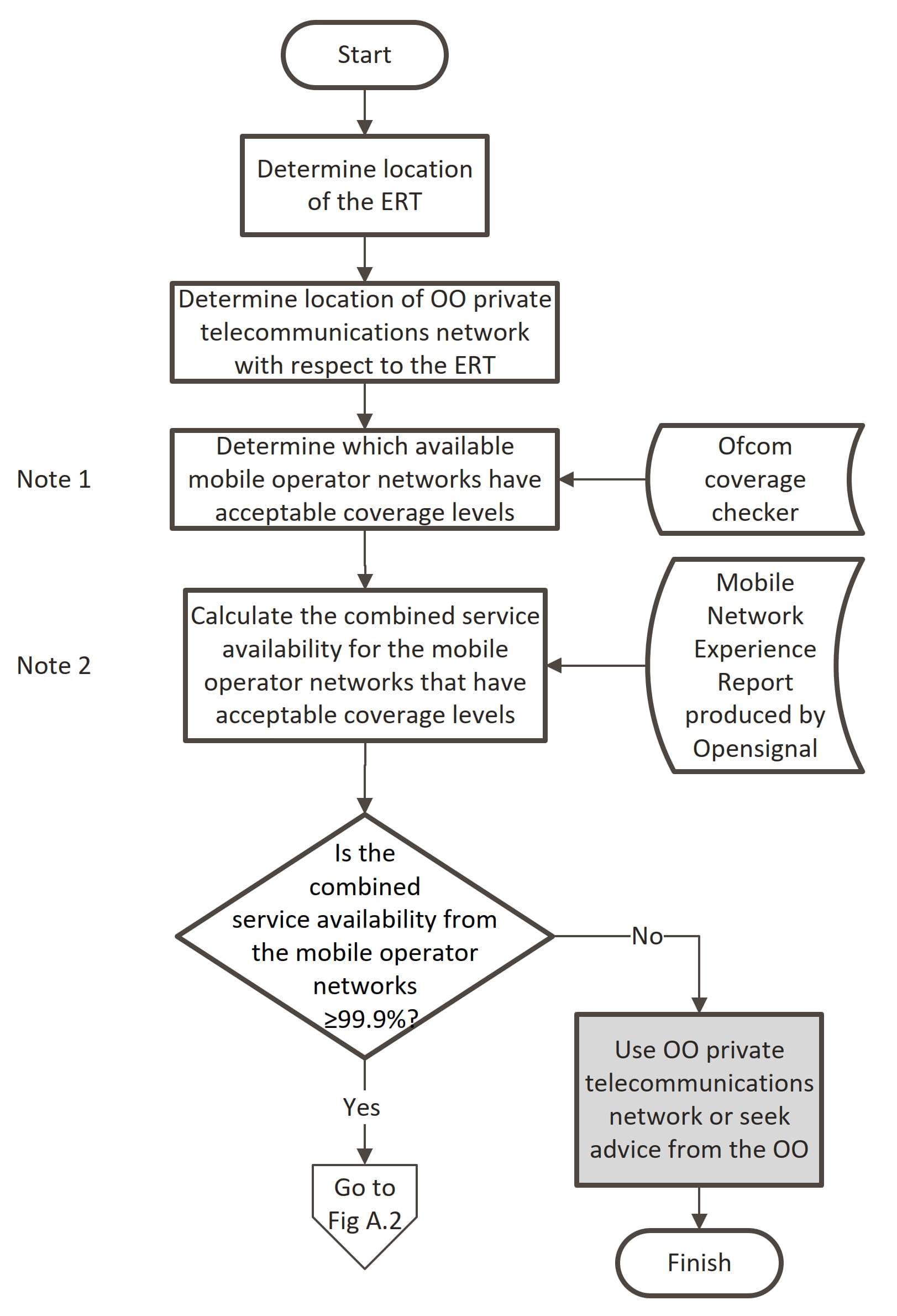
A1 Note 1 - Determine predicted coverage levels for each mobile operator
The predicted coverage level for each mobile operator is determined using Ofcom mobile coverage checker [Ref 1.I].
An acceptable predicted coverage level on the Ofcom mobile coverage checker is when the outdoor voice service is shown as "OK coverage".
Online websites are available to convert national grid references into post code areas.
A2 Note 2 - Determine the combined service availability for the mobile operators
The service availability for each mobile operator that provides an acceptable predicted coverage level is determined by using the latest Mobile Network Experience Report produced by Opensignal.
The combined service availability for a service that is provided by more than one mobile operator is determined as shown in Equation A.1.
Equation A.1 Combined service availability provided by more than one mobile operator.
where:
X is combined service availability
A is service availability of mobile operator i over a minimum 90 days
n is the number of mobile operators with an acceptable predicted coverage at that location
i is the identifier of the mobile operator, for example A1 is the first operator
Equation A.1 relies on the service availability percentage figures being entered in decimal form.