Design Manual for Roads and Bridges


Drainage
Design
CD 533 Determination of pipe and bedding combinations for drainage works
(formerly HA 40/01)
Version 1.1.0
Summary
This document contains requirements and guidance for selecting suitable combinations of drainage pipes and bedding types to meet given loading requirements.
Application by Overseeing Organisations
Any specific requirements for Overseeing Organisations alternative or supplementary to those given in this document are given in National Application Annexes to this document.
Feedback and Enquiries
Users of this document are encouraged to raise any enquiries and/or provide feedback on the content and usage of this document to the dedicated National Highways team. The email address for all enquiries and feedback is: Standards_Enquiries@highwaysengland.co.uk.
This is a controlled document.Latest release notes
| Document Code | Version number | Date of publication of relevant change | Changes made to | Type of change |
|---|---|---|---|---|
| CD 533 | 1.1.0 | December 2021 | Core document | Incremental change to requirements |
| Incremental changes to some requirement clauses and numerous editorial amendments. | ||||
Previous versions
| Document Code | Version number | Date of publication of relevant change | Changes made to | Type of change |
|---|---|---|---|---|
| CD 533 | 1.0.0 | March 2020 | ||
| CD 533 | 0 | December 2019 |
Foreword
Publishing information
This document is published by National Highways.
This document supersedes HA 40/01, which is withdrawn.
Contractual and legal considerations
This document forms part of the works specification. It does not purport to include all the necessary provisions of a contract. Users are responsible for applying all appropriate documents applicable to their contract.
Introduction
Background
The requirements and advice given in this document are based upon the guidance in BS EN 1295-1 [Ref 22.N]. Further guidance for the structural design of buried pipelines in the UK can be found in BS 9295 2010 [Ref 7.N].
BS EN 1295-1 [Ref 22.N] contains a National Annex A which states the vehicle loadings to be used for pipeline design. These loadings were derived from BS 5400-2 2006 [Ref 21.N], which has since been revised. The loadings reported in BS 5400-2 2006 [Ref 21.N] are still employed in pipeline design as they give a more conservative result than loadings derived from newer standards.
The charts and tables given at the appendices are based on BS 5400-2 2006 [Ref 21.N] and BS 9295 2010 [Ref 7.N]. These charts and tables provide a simplified method for defining the pipe and bedding combinations required for permitted vehicle loading requirements and to be compliant with the range of permitted combinations given in MCHW Series 0500 [Ref 9.N] and MCHW HCD Series F [Ref 11.N].
MCHW Series 0500 [Ref 9.N] permits a range of pipes of different material properties to be used for drainage works in highways. MCHW HCD Series F [Ref 11.N] also allows a choice in the method of bedding pipes where the degree of structural support given to the pipe when it is laid in a trench varies. Not all possible combinations of pipe and bedding selected from the permitted options will be suitable for a particular design solution. Permitted combinations are therefore specified for each contract.The charts given in the appendices to this document are intended for a wide range of pipe bedding combinations for a range of manufactured pipe thicknesses, possible trench widths and bedding factors.
Assumptions made in the preparation of this document
The assumptions made in GG 101 [Ref 8.N] apply to this document.
Abbreviations and symbols
| Abbreviation | Definition |
|---|---|
| HCD | Highway construction details |
| MCHW | Manual of Contract Documents for Highway Works |
| SDR | Standard dimensional ratio |
| SHW | Specification for Highway Works (MCHW Vol. 1) |
| Symbol | Definition |
|---|---|
| Modulus of Elasticity | |
| Bedding factor for a pipe in trench | |
| Design factor of safety | |
| Total load imposed on a pipe at given depth | |
| Safe supporting strength of a pipe/bed combination | |
| Crushing strength as given by relevant British Standard |
Terms and definitions
| Term | Definition |
|---|---|
| Bedding factor | Bedding factor ( ) is a multiple by which stresses in the pipe are reduced by the load spreading properties of the bedding. |
| Flexible pipes | pipes that deform to a significant extent before collapse |
| HA and HB loading | HA loading is loading representing normal traffic in Great Britain. HB loading is an abnormal vehicle unit loading (source: DMRB CS 454 [Ref 1.I]). |
| Main road loading | Main road loading consists of 45 units of Type HB loading to BS 5400-2 2006 [Ref 21.N]. Field loading consists of two wheels of 60 kN with contact pressure 400 kN/m2 . See Young & O'Reilly (TRRL) [Ref 1.N] |
| Rigid pipes | Pipes that fracture before significant deformation occurs |
1. Scope
Aspects covered
1.1 The design and selection of type of pipe and bedding to meet the loading requirements from the permitted alternatives in MCHW Series 0500 [Ref 9.N] shall be in accordance with:
- the requirements in BS 9295 2010 [Ref 7.N]; or,
- the requirements in Sections 2 and 3.
NOTE The requirements presented in Sections 2 and 3, in addition to the associated design charts and guidance presented in Appendix A to this document, provide a simplified method for selecting pipe and bedding combinations.
1.2 This document shall apply to the following type of pipes:
- vitrified clay pipes to BS EN 295-1 [Ref 25.N] to classes L 95, 120, 160 and 200, See BS 65 [Ref 26.N];
- precast concrete pipes classes to the following standards:
-
- BS 5911-1 [Ref 3.N];
- BS 5911-5 [Ref 2.N] (pre-stressed non pressure pipes and fittings); and,
- BS EN 1916 [Ref 4.N];
- thermoplastic pipes to the following standards:
-
- BS 4660 [Ref 24.N] (size 110 mm & 160 mm diameter);
- BS EN ISO 1452-1 [Ref 19.N];
- BS EN 1401-1 [Ref 12.N];
- BS EN 1852-1 [Ref 15.N];
- BS EN 12666-1 [Ref 14.N];
- BS EN 13476-1 [Ref 16.N];
- BS EN 13476-2 [Ref 17.N]; and,
- BS EN 13476-3 [Ref 18.N]
- ductile-iron pipes to BS EN 598 [Ref 6.N];
- cast-iron pipes to BS 437 [Ref 20.N]; and,
- glass reinforced plastic (GRP) pipes to BS EN 14364 [Ref 13.N].
NOTE Refer to Appendix A for Figures A.1, A.2 and A.3 which detail bedding/pipe combinations.
1.3 Hydraulic design requirements for pipes are not covered in this document and shall be in accordance with DMRB CG 501 [Ref 5.N].
1.4 This document shall apply to pipes up to 900 mm internal diameter.
1.5 Pipes greater than 900 mm diameter, or multi-cellular pipe structures, shall be designed with reference to DMRB CG 300 [Ref 23.N].
Implementation
1.6 This document shall be implemented forthwith on all schemes involving the use of buried pipes on the Overseeing Organisations' motorway and all-purpose trunk roads according to the implementation requirements of GG 101 [Ref 8.N].
Use of GG 101
1.7 The requirements contained in GG 101 [Ref 8.N] shall be followed in respect of activities covered by this document.
2. Design approach for selecting pipe and bedding combinations
2.1 A schedule containing the permitted pipe/bed combinations for carrier drains and filter drains for a project shall be prepared for contract specific Appendix 5/1 of the MCHW Series 0500 [Ref 9.N].
NOTE An example of a format for the permitted pipe/bed combinations for carrier drains and filter drains schedule, "Group numbers for determining allowable pipes" is given in Appendix B.
2.2 Where the charts of bedding/pipe combinations provided in Appendix A are applied to the design of pipe types not listed in the scope section of this document, the design of bedding/pipe combinations shall be in accordance with the requirements of BS 9295 2010 [Ref 7.N].
3. Design of pipe and bedding combinations for drainage works
Range of bedding types
3.1 Bed type materials shall be specified in accordance with MCHW Series 0500 [Ref 9.N].
3.1.1 Bed types A, B, F, N and S shown in the HCD drawing "Surface Water Drains" MCHW HCD Series F [Ref 11.N] should be specified for rigid pipes and bed types S and T with flexible pipes.
NOTE 1 Type Z is for use with any type of pipe for permanent protection against mechanical damage.
NOTE 2 Type T bedding for rigid pipes is less likely to be economic for the same degree of support.
NOTE 3 Pipe bedding detail is given in the drawings for carrier drains and filter drains MCHW HCD Series F [Ref 11.N].
NOTE 4 Different bedding combinations provide varying degrees of support to the pipe. In the case of combined surface and sub-surface drains the granular bedding and surround additionally functions as a filter medium.
3.2 Flexibly jointed pipes shall be specified with a compressible filler to break the Type Z surround at every joint or second joint for pipes shorter than standard proprietary length.
NOTE 1 All bed types shown in the drawing "Filter Drains" MCHW HCD Series F [Ref 11.N] are suitable for both rigid and flexible pipes.
NOTE 2 The specification requirements for bedding, backfill material and construction are given in MCHW Series 0500 [Ref 9.N].
Loading on pipes
3.3 Main road loading (which include motorways and all-purpose trunk roads) shall be applicable to pipes under pavements including cross drains and for pipes in verges where heavy loads can occur.
3.4 Main road loading shall consist of eight wheel loads, each of 112.5 kN including impact factor, in the HB loading pattern corresponding to 45 units of HB loading in accordance with BS 5400-2 2006 [Ref 21.N] as reflected by BS 9295 2010 [Ref 7.N].
3.5 Field loading shall apply to fields and lightly trafficked access tracks.
3.6 Field loading shall consist of two wheels 1.0 m apart each of a static load of 30 kN with an impact factor of 2.0 giving a total load for each wheel of 60 kN.
3.7 Filter drain loading shall be applicable to pipes in filter drains in verges and central reserves.
3.8 Filter drain loading shall correspond to outer verge loading specified with 30 units of HB loading with each wheel load being 62.5 kN.
3.9 Only two wheel loads shall be used for filter drain loading but with an increased impact factor of 1.4 giving a total load for each wheel of 87.5 kN.
3.9.1 Filter drains not immediately adjacent to the carriageway may be designed for field loads.
3.10 Water loads, that is the weight of the pipe content, shall only apply to pipes greater than 600 mm internal diameter.
NOTE The design charts, included in Appendix A, Figures A.1 to A.3, cater for three categories of loading conditions which include imposed surface loads together with soil and water loads as appropriate.
Loads during construction
3.11 Where imposed loads during construction exceed normal in-service loads, the design charts in Appendix A of this document shall not be used.
3.12 Where pipes laid under and adjacent to roads are subject to higher loads during construction, guidance shall be followed from: "A Guide to Design Loadings for Buried Rigid Pipes" by Young & O'Reilly (TRRL) [Ref 1.N], BS 9295 2010 [Ref 7.N] or BS EN 1295-1 [Ref 22.N].
Settlement
3.13 Where pipes are bedded in highly compressible soil, granular beds (types B, F and S) shall be used.
3.14 Where pipes are bedded in highly compressible soil, geotextile filter in accordance with MCHW Series 0600 [Ref 10.N] shall be used on the base of the trench to prevent contamination of the bedding material.
Rigid pipe design
3.15 Rigid pipes shall be designed either in accordance with BS 9295 2010 [Ref 7.N] or with the design charts in Appendix B.
NOTE 1 Rigid pipes are those which fracture before significant deformation occurs (such as those of clayware, and concrete).
NOTE 2 The derivation of the design charts for rigid pipes in this document is in accordance with the principles given in "A Guide to Design Loadings for Buried Rigid Pipes" Young & O'Reilly (TRRL) [Ref 1.N] and "Simplified Tables of External Loads on Buried Pipelines" Young, Brennan & O'Reilly (TRRL) [Ref 3.I]).
3.15.1 Reference should be made to "A Guide to Design Loadings for Buried Rigid Pipes" Young & O'Reilly (TRRL) [Ref 1.N] and "Simplified Tables of External Loads on Buried Pipelines" Young, Brennan & O'Reilly (TRRL) [Ref 3.I] for the full theory and for the design of special cases not covered by the appendices to this document.
3.16 The safe supporting strength of the pipe/bed combination shall be given by Equation 3.16:
Equation 3.16 Safe supporting strength of the pipe/bed combination
| where: | |
| = crushing strength | |
| = bedding factor | |
| = factor of safety taken as 1.25 |
3.17 The allowable depth range of the pipes shall be determined such that , where is the total load on a particular pipe at a given depth.
3.18 The load on the pipe shall be found with the “narrow trench” equation, as defined in "A Guide to Design Loadings for Buried Rigid Pipes" Young & O'Reilly (TRRL) [Ref 1.N].
NOTE The load on the pipe is directly related to the trench width. Thus if the width of trench constructed exceeds the assumed design width then the load on the pipe is likely greater than the design load.
3.19 Where the "narrow trench" equation is used for pipes greater than 375 mm internal pipe diameter, the trench width shall be taken as at least 700 mm greater than the pipe outside diameter. See Young & O'Reilly (TRRL) [Ref 1.N].
3.20 For all pipes below 375 mm internal diameter the “wide trench” equation (see Young & O'Reilly (TRRL) [Ref 1.N] ) shall be used to calculate the load on the pipe, and in this case no restriction on the trench width is necessary.
Bedding factor
Carrier drains (HCD drawing, surface water drains - trench and bedding details)
3.21 The bedding factors for rigid pipe design shall be in accordance with BS EN 1295-1 [Ref 22.N] which are summarised in Table 3.21N2.
NOTE 1 The bedding factor is the ratio of the failure load for the pipe installed in the ground to its failure load in a crushing test machine and is generally greater than unity.
NOTE 2 The bedding factors in Table 3.21 N2 , which have been taken from BS EN 1295-1 [Ref 22.N], are the values of the bedding factors that have been assumed for the bed types shown in MCHW HCD Series F [Ref 11.N].
Bed type |
Description |
Bedding factor |
|---|---|---|
| A | concrete bed | 2.6 |
| B | granular bed & haunch | 1.9 |
| F | granular bed | 1.5 |
| N | granular or sandy bed | 1.1 |
| S | granular surround | 2.2 |
3.21.1 Though not constituting a bedding type in accordance with BS EN 1295-1 [Ref 22.N], the bed type Z "concrete surround" , may have an assumed bedding factor of 2.6.
Filter drains (HCD drawing, filter drains - trench and bedding details)
3.22 A bedding factor of 1.9 shall be used for bed types I, K and M in MCHW HCD Series F [Ref 11.N].
NOTE A bedding factor of 1.9 is used in order to allow for the full range of likely filter material.
3.23 A bedding factor of 2.2 shall be used for bed type H in MCHW HCD Series F [Ref 11.N].
3.24 A bedding factor of 2.6 shall be used for bed types G, J and L MCHW HCD Series F [Ref 11.N].
Flexible pipe design
3.25 Flexible pipes shall be designed in accordance with BS 9295 2010 [Ref 7.N] and BS EN 1295-1 [Ref 22.N], or in accordance with the MCHW Series 0500 [Ref 9.N].
NOTE 1 Flexible pipes are those which deform to a significant extent before collapse (such as those in plastics, or steel).
NOTE 2 Commonly, flexible pipes used for highway drainage are manufactured from thermoplastic materials.
NOTE 3 The design charts in Appendix A are based on a design method in BS EN 1295-1 [Ref 22.N] for flexible pipes which takes into account the relative stiffness of the pipe and the surrounding soil.
3.26 A maximum ring deflection (that is, change in diameter) of 5% and a factor of safety against ring buckling of 2 shall be used to obtain the safe depth ranges.
3.26.1 The pipe bed surround E values provided in Table 3.26.1N1 should be used in the design process for the design of flexible pipes provided in BS 9295 2010 [Ref 7.N] and BS EN 1295-1 [Ref 22.N].
NOTE 1 The degree of compaction of the pipe bedding material has a significant effect on the results and consequently the worst case, with the material in a loose condition, has been assumed. The corresponding E values used are provided in Table 3.26.1N1.
| Bed type | Description | Surround E value |
|---|---|---|
| S (HCD Surface Water Drains Drawing) | granular surround | 5 MPa |
| T (HCD Surface Water Drains Drawing) | sandy surround | 2 MPa |
| All (HCD Filter Drains Drawing) | filter drains | 5 MPa |
NOTE 2 The strength of a thermoplastic pipe is a function of the initial pipe stiffness and the modulus E of the native soil material through which the trench has been excavated, and that of the pipe bedding and surround. The compaction of the sidefill material is, therefore, fundamental to the performance of flexible/semi rigid pipes.
Design assumptions
3.27 The design assumptions in this section shall be used when designing pipe/bedding combinations with the charts in Appendix A.
3.27.1 Class T bedding should not be specified for main road loading situations.
NOTE Granular bedding material is deemed to be relatively self compacting and provide adequate support with minimal compaction. It is the preferred bedding material
3.28 The embedment for semi-rigid and flexible pipes shall be as set out in Table NA8 of BS EN 1295-1 [Ref 22.N].
NOTE Thermoplastic pipes principally comprise those manufactured from PVC-u, polyethylene and polypropylene, though there are variations. The performance of each polymer is different and is dependent on the initial pipe stiffness, and the creep ratio.
Withdrawal of trench supports during backfilling
3.29 Coefficients for soil modulus and bedding angle of friction relating to the removal of trench support systems shall be in accordance with BS 9295 2010 [Ref 7.N].
NOTE 1 The withdrawal of trench support systems is usually completed in stages.
NOTE 2 When pipes are laid in trenches where the sides are supported by trench support systems, the values of the soil modulus and the bedding angle of friction are reduced by a coefficient depending on the stage during the backfill process at which the support system is withdrawn.
3.29.1 Where trench support systems are withdrawn in stages before each layer of backfill is compacted, the friction coefficient should be taken as unity.
3.29.2 Where trench support systems are removed in stages after the backfill is compacted, the friction coefficient should be taken as 0.6.
NOTE A friction coefficient of 0.6, for when trench support systems are removed in steps after the backfill is compacted, is recommended by most pipe manufacturers.
3.29.3 Where the trench support systems are withdrawn after the trench is completely backfilled, the friction coefficient should be taken as 0.2.
3.29.4 Withdrawing trench support systems after the trench is completely backfilled should be avoided.
4. Normative references
The following documents, in whole or in part, are normative references for this document and are indispensable for its application. For dated references, only the edition cited applies. For undated references, the latest edition of the referenced document (including any amendments) applies.
| Ref. | Document |
|---|---|
| Ref 1.N | HMSO. Young, OC & O'Reilly, MP. Young & O'Reilly (TRRL), 'A Guide to Design Loadings for Buried Rigid Pipes' |
| Ref 2.N | BSI. BS 5911-5, 'Concrete pipes and ancillary concrete products. Specification for pre-stressed non-pressure pipes and fittings with flexible joints' |
| Ref 3.N | BSI. BS 5911-1, 'Concrete pipes and ancillary concrete products. Specification for unreinforced and reinforced concrete pipes (including jacking pipes) and fittings with flexible joints (complementary to BS EN 1916:2002)' |
| Ref 4.N | BSI. BS EN 1916, 'Concrete pipes and fittings, unreinforced, steel fibre and reinforced (Designated Standard - CPR)' |
| Ref 5.N | National Highways. CG 501, 'Design of highway drainage systems' |
| Ref 6.N | BSI. BS EN 598, 'Ductile Iron Pipes & Fittings for Sewerage Applications. (Designated Standard - CPR)' |
| Ref 7.N | BSI. BS 9295, 'Guide to the structural design of buried pipelines' , 2010 |
| Ref 8.N | National Highways. GG 101, 'Introduction to the Design Manual for Roads and Bridges' |
| Ref 9.N | Highways England. MCHW Series 0500, 'Manual of Contract Documents for Highway Works, Volume 1 Specification for Highway Works. Series 500 Drainage and service ducts.' |
| Ref 10.N | Highways England. MCHW Series 0600, 'Manual of Contract Documents for Highway Works, Volume 1 Specification for Highway Works. Series 600 Earthworks' |
| Ref 11.N | Highways England. MCHW HCD Series F, 'MCHW Volume 3: HCD Section 1 Series F - Drainage' |
| Ref 12.N | BSI. BS EN 1401-1 , 'Plastic piping systems for non-pressure underground drainage and sewerage. (PVC-U)' |
| Ref 13.N | BSI. BS EN 14364, 'Plastics piping systems for drainage and sewerage with or without pressure. Glass-reinforced thermosetting plastics (GRP) based on unsaturated polyester resin (UP). Specifications for pipes, fittings and joints' |
| Ref 14.N | BSI. BS EN 12666-1, 'Plastics piping systems for non-pressure underground drainage and sewerage. Polyethylene (PE). Specifications for pipes, fittings and the system' |
| Ref 15.N | BSI. BS EN 1852-1, 'Plastics piping systems for non-pressure underground drainage and sewerage. Polypropylene (PP). Specifications for pipes, fittings and the system' |
| Ref 16.N | BSI. BS EN 13476-1, 'Plastics piping systems for non-pressure underground drainage and sewerage. Structured-wall piping systems of unplasticized poly(vinyl chloride) (PVC-U), polypropylene (PP) and polyethylene (PE). General requirements and performance characteristics' |
| Ref 17.N | BSI. BS EN 13476-2, 'Plastics piping systems for non-pressure underground drainage and sewerage. Structured-wall piping systems of unplasticized poly(vinyl chloride) (PVC-U), polypropylene (PP) and polyethylene (PE). Specifications for pipes and fittings with smooth internal and external surface and the system, Type A' |
| Ref 18.N | BSI. BS EN 13476-3, 'Plastics piping systems for non-pressure underground drainage and sewerage. Structured-wall piping systems of unplasticized poly(vinyl chloride) (PVC-U), polypropylene (PP) and polyethylene (PE). Specifications for pipes and fittings with smooth internal and profiled external surface and the system, Type B ' |
| Ref 19.N | BSI. BS EN ISO 1452-1, 'Plastics piping systems for water supply and for buried and above-ground drainage and sewerage under pressure. Un-plasticized poly (vinyl chloride) (PVC U)' |
| Ref 20.N | BSI. BS 437, 'Specification for cast iron drain pipes, fittings and their joints for socketed and socketless systems' |
| Ref 21.N | BSI. BS 5400-2, 'Steel, concrete and composite bridges. Specification for loads' , 2006 |
| Ref 22.N | BSI. BS EN 1295-1, 'Structural design of buried pipelines under various conditions of loading. General requirements' |
| Ref 23.N | National Highways. CG 300, 'Technical approval of highway structures' |
| Ref 24.N | BSI. BS 4660, 'Thermoplastics ancillary fittings of nominal sizes 110 and 160 for below ground gravity drainage and sewerage' |
| Ref 25.N | BSI. BS EN 295-1, 'Vitrified clay pipe systems for drains and sewers: Requirements for pipes, fittings and joints (Designated Standard - CPR)' |
| Ref 26.N | BSI. BS 65 , 'Vitrified clay pipes, fittings and ducts, also flexible mechanical joints for use solely with surface water pipes and fittings' |
5. Informative references
The following documents are informative references for this document and provide supporting information.
| Ref. | Document |
|---|---|
| Ref 1.I | National Highways. CS 454, 'Assessment of highway bridges and structures' |
| Ref 2.I | Water Services Association and Foundation for Water Research, 1993. Pipeline Technology Group. WSA 1993, 'Materials Selection Manual for Sewers, Pumping Mains and Manholes' |
| Ref 3.I | HMSO. Young, OC, Brennan, G & O'Reilly, MP. Young, Brennan & O'Reilly (TRRL), 'Simplified Tables of External Loads on Buried Pipelines' |
Appendix A. Charts of bedding/pipe combinations
A1 Types of pipe to which charts are applicable
The charts of "bedding/pipe combinations" are shown in Figures A.1, A.2 and A.3 below. These are applicable to the types of pipe defined in Section 1, Scope.
Appendix B. Group numbers for determining allowable pipe / bed combinations
| Rigid | |||||||||||||||||
|---|---|---|---|---|---|---|---|---|---|---|---|---|---|---|---|---|---|
| Pipe material | Vitrified clay | Concrete | |||||||||||||||
| Pipe class | 160 | 200 | 120 | ||||||||||||||
| Bed type | A | S | B | F | N | A | S | B | F | N | A | S | B | F | N | ||
| Nominal pipe diameter (mm) |
100 | 15 | 15 | 15 | 15 | 15 | 15 | 15 | 15 | 15 | 15 | ||||||
| 150 | 15 | 15 | 15 | 15 | 12 | 15 | 15 | 15 | 15 | 14 | |||||||
| 200 | 15 | 15 | 15 | 14 | 5 | 15 | 15 | 15 | 15 | 14 | |||||||
| 225 | 15 | 15 | 15 | 14 | 5 | 15 | 15 | 15 | 15 | 10 | |||||||
| 250 | 15 | 15 | 15 | 14 | 5 | 15 | 15 | 15 | 15 | 10 | |||||||
| 300 | 15 | 15 | 15 | 15 | 6 | 15 | 15 | 15 | 15 | 10 | 15 | 15 | 12 | 6 | 1 | ||
| 375 | 15 | 15 | 15 | 15 | 7 | 15 | 15 | 15 | 15 | 11 | 15 | 14 | 15 | 6 | 1 | ||
| 400 | 15 | 15 | 15 | 15 | 6 | 15 | 15 | 15 | 15 | 11 | |||||||
| 450 | 15 | 15 | 15 | 15 | 7 | 15 | 14 | 10 | 4 | ||||||||
| 500 | 15 | 15 | 15 | 15 | 7 | ||||||||||||
| 525 | 15 | 14 | 10 | 4 | |||||||||||||
| 600 | 15 | 15 | 12 | 5 | 1 | ||||||||||||
| 675 | 15 | 15 | 12 | 5 | 1 | ||||||||||||
| 700 | |||||||||||||||||
| 750 | 15 | 15 | 12 | 5 | 1 | ||||||||||||
| 800 | |||||||||||||||||
| 825 | 15 | 14 | 11 | 5 | 1 | ||||||||||||
| 900 | 15 | 14 | 12 | 7 | 2 | ||||||||||||
| Non-rigid | |||||||||||||||
|---|---|---|---|---|---|---|---|---|---|---|---|---|---|---|---|
| Semi-rigid | Flexible/Thermoplastic | ||||||||||||||
| Pipe Material | GRP | Ductile Iron | Stiffness > 6 kPa | Others by design | |||||||||||
| Pipe Class | 5 kN/m2 | 10 kN/m2 | K9 | PVCu | PP/PE | max soil E < 5 | |||||||||
| Bed Type | S | T | S | T | S | T | S | T | S | T | 4 pvc | 8 pe | |||
| Nominal pipe diameter (mm) |
100 | 15 | 15 | 15 | 14 | 14 | 12 | 13 | 13 | 14 | SDR 41 pipes are specified by external diameter. The nominal diameters shown are the nearest equivalent internal diameter. |
||||
| 150 | 15 | 15 | 15 | 14 | 13 | 12 | 10 | 13 | 14 | ||||||
| 200 | 15 | 15 | 15 | 14 | 10 | 12 | 8 | 13 | 14 | ||||||
| 250 | 15 | 15 | 15 | 14 | 10 | 12 | 8 | 13 | 14 | ||||||
| 800 | 15 | 15 | 15 | 14 | 7 | 12 | 7 | 13 | 14 | ||||||
| 900 | 15 | 15 | 15 | 14 | 7 | 12 | 5 | 13 | 14 | ||||||
| 300 | 15 | 15 | 15 | 14 | 9 | 12 | 8 | 13 | 14 | ||||||
| 350 | 15 | 15 | 15 | 14 | 9 | 12 | 8 | 13 | 14 | ||||||
| 400 | 15 | 15 | 15 | 14 | 9 | 12 | 7 | 13 | 14 | ||||||
| 500 | 15 | 15 | 15 | 14 | 9 | 12 | 7 | 13 | 14 | ||||||
| 600 | 15 | 15 | 15 | 14 | 7 | 12 | 7 | 13 | 14 | ||||||
| 700 | 15 | 15 | 15 | 14 | 7 | 12 | 7 | 13 | 14 | ||||||
| Pipe material | Vitrified clay | Concrete | Thermoplastic | |||||||
|---|---|---|---|---|---|---|---|---|---|---|
| Pipe Class | 160 | 200 | 120 | Structured wall | SDR 41 |
|||||
| Nominal pipe diameter (mm) |
100 | 15 | 15 | 15 | 100 | Nominal pipe diameter (mm) |
||||
| 150 | 15 | 15 | 15 | 15 | 110 | |||||
| 225 | 15 | 15 | 15 | 150 | ||||||
| 250 | 15 | 15 | 15 | 15 | 160 | |||||
| 300 | 15 | 15 | 15 | 15 | 15 | 200 | ||||
| 350 | 15 | 225 | ||||||||
| 375 | 15 | 15 | 15 | 15 | 250 | |||||
| 400 | 15 | 15 | 15 | 260 | ||||||
| 450 | 15 | 15 | 15 | 15 | 300 | |||||
| 500 | 11 | 15 | 15 | 360 | ||||||
| 525 | 15 | 15 | 400 | |||||||
| 600 | 11 | 15 | 15 | 450 | ||||||
| 675 | 15 | 15 | 500 | |||||||
| 700 | 15 | 600 | ||||||||
| 750 | 15 | 15 | 700 | |||||||
| 800 | 15 | 750 | ||||||||
| 825 | 15 | 15 | 900 | |||||||
| 900 | 15 | |||||||||
| Pipe Diameter (mm) | Pipe group no. | Vitrified clay | Concrete | Ductile iron | GRP | Thermoplastic | ||
|---|---|---|---|---|---|---|---|---|
| 160 | 200 | 120 | Structured wall | SDR 41 | ||||
| 150 | 2 | ASBFN | ASBFN | ST | ST | |||
| 160 | 5 | ST | ||||||
| 150 | 5 | ASBFN | ASBFN | ST | ST | |||
| 200 | 7 | ST | ST | ST | ||||
| 225 | 2 | ASBFN | ASBFN | ST | ||||
| 225 | 7 | ASBF | ASBFN | ST | ||||
| 300 | 4 | ASBFN | ASBFN | ASB | ST | ST | ST | |
| 400 | 8 | ASBF | ASBFN | ST | ST | ST | ||
| 600 | 7 | ASB | ST | ST | ST | |||
| 750 | 11 | ASB | ST | |||||
| Drain type (lower trench) Refer to HCD drawings or Contract Drg nr: |
Drain type (surface level) Refer to HCD drawings or Contract Drg nr: |
Pipe diameter (mm) | Pipe group number | Vitrified clay | Precast concrete | Thermoplastic | ||
|---|---|---|---|---|---|---|---|---|
| 160 | 200 | 120 | Structured Wall | SDR41 | ||||
| G,H,I |
W | 150 | 4 | |||||
| M,L |
225 | 8 | ||||||
| J,K |
Specify in contract | 250 | 2 | |||||
Appendix C. Worked example
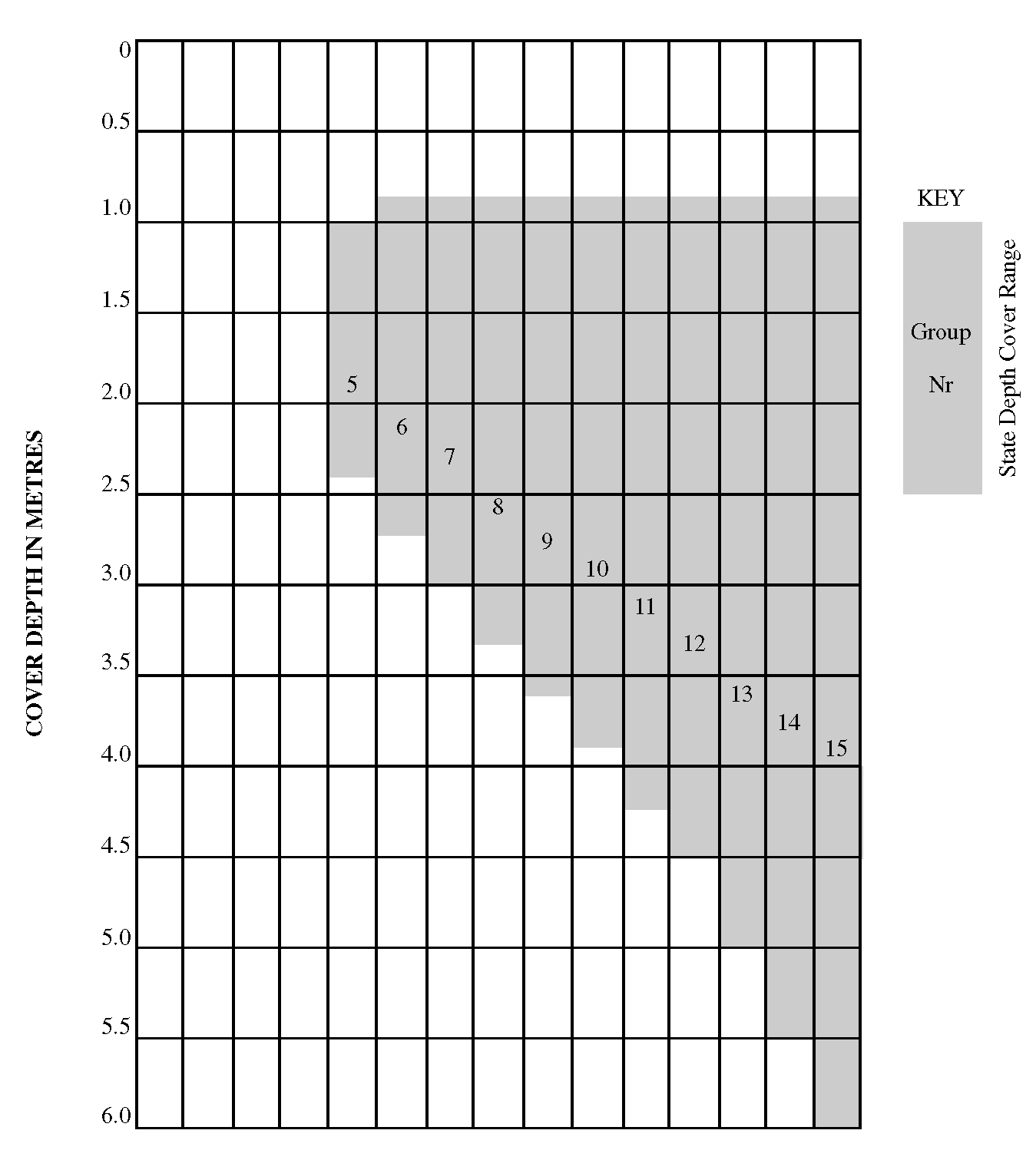
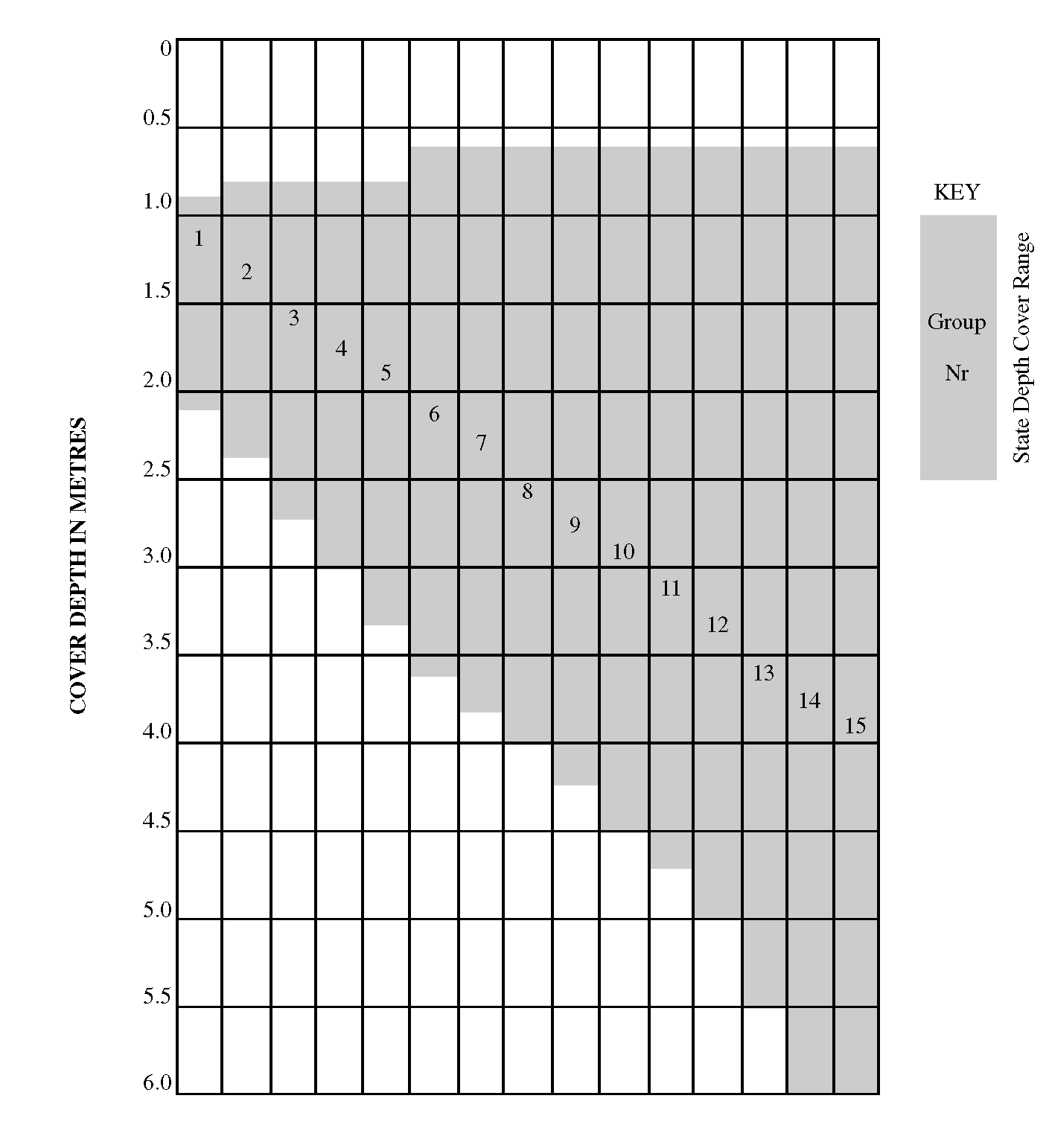
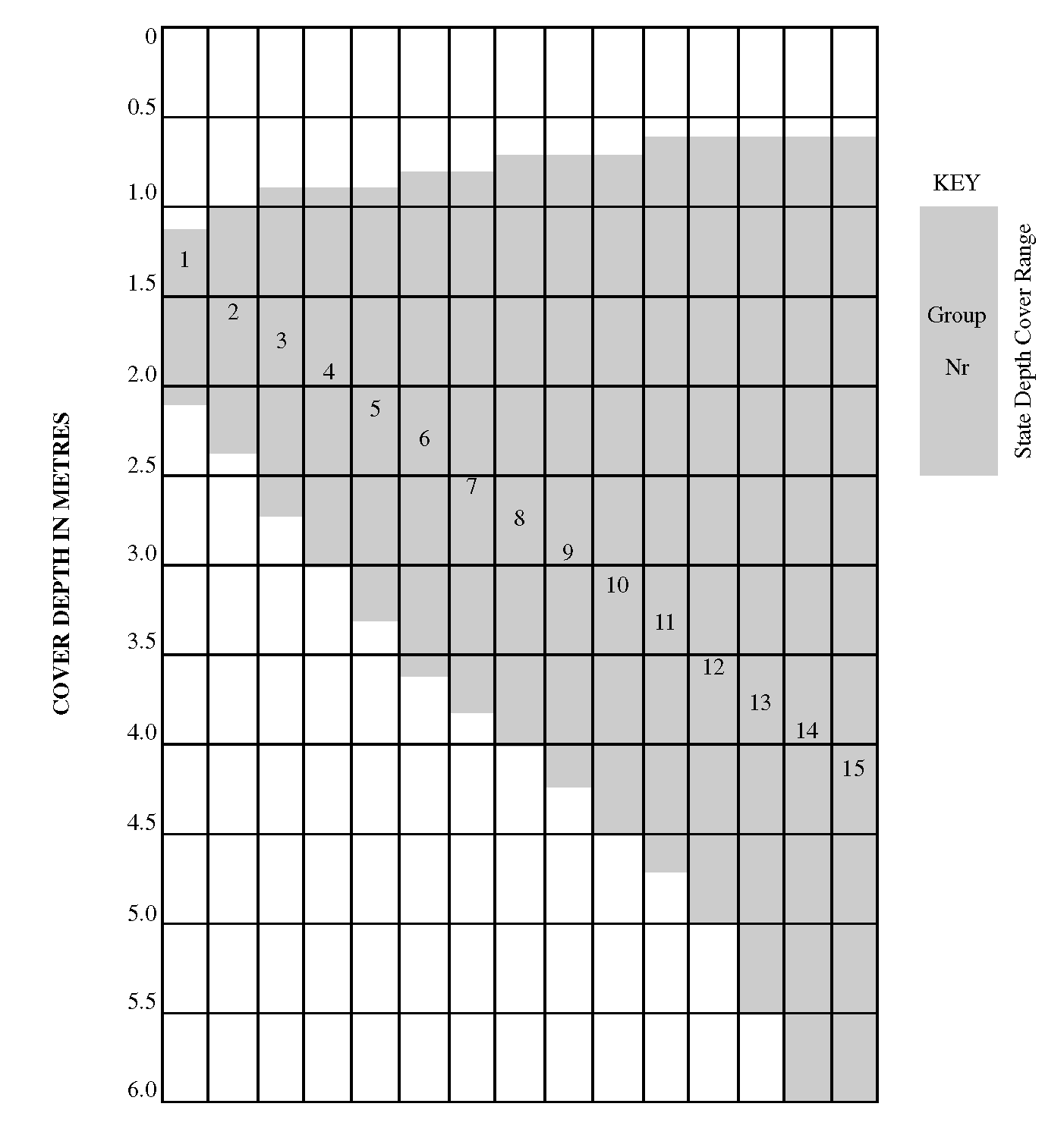
The design charts for determining safe pipe/bedding combinations are given in Appendix A. Figures A.1, A.2 and A.3 of Appendix A are used to determine a pipe group number for three categories of loading corresponding to main road, field and filter drain loadings respectively. Having determined the group number, Figures B.1, B.2 or B.3 from Appendix B are then used to obtain the safe combination for carrier drains or filter drains respectively.
As an example, consider a carrier pipe 300 mm in diameter located in the carriageway verge with depth of cover of 2.0 m minimum and 3.0 m maximum.
For the location of the pipe it is decided that main road loading should be assumed and therefore Figure A.1 would be applicable.
From Figure A.1 the group number corresponding to the minimum and maximum depth of cover to the pipe is found to be group 7.
From Figure B.1 the permitted combinations are indicated by those having group numbers greater than or equal to 7. For a 300 mm diameter pipe these are found to be:
| Pipe | Class | Bedding type |
|---|---|---|
| Vitrified clay | 160 | A,S,B,F |
| 200 | A,S,B,F,N | |
| Precast concrete | 120 | A,S,B |
| Thermoplastic | S,T |
For filter drains the procedure is similar except that the bedding strength provided by all filter drain types shown in the MCHW HCD Series F [Ref 11.N] is acceptable. Thus the design is a check on the suitability of the pipe for the given loading.
Using the previous example of a 300 mm diameter pipe from Figure A.3 the group number is found to be 4. From Figure B.3 suitable pipes for a group number equal to or greater than 4 are found to be:
| Pipe | Class |
|---|---|
| Vitrified clay | 160 |
| 200 | |
| Precast concrete | 120 |
| Thermoplastic | Various |
It should be noted that in Tables B.1, B.2 and B.3 (Appendix B) where some group numbers are omitted it is because either the particular class of pipe is not usually manufactured in that diameter or that the strength of the given pipe bed combination is insufficient.
When the properties of pipe materials are known, the methods detailed in the "Materials Selection Manual for Sewers, Pumping Mains and Manholes" WSA 1993 [Ref 2.I] may be used to verify the suitability of the pipes in accordance with the schedule in Appendix 5/1 of MCHW Series 0500 [Ref 9.N].