Design Manual for Roads and Bridges


Road Layout
Design
CD 116 Geometric design of roundabouts
(formerly TD 16/07, TD 50/04, TD 51/17, TD 54/07, TA 23/81, TA 78/97, TA 86/03, TD 70/08)
Version 2.1.0
Summary
This document provides requirements for the geometric design of roundabouts.
National Variation
This document has associated National Application Annexes providing alternative or supplementary content to that given in the core document, which is relevant to specific Overseeing Organisations. National Application Annexes are adjoined at the end of this document.
Feedback and Enquiries
Users of this document are encouraged to raise any enquiries and/or provide feedback on the content and usage of this document to the dedicated National Highways team. The online feedback form for all enquiries and feedback can be accessed at: www.standardsforhighways.co.uk/feedback.
This is a controlled document.Latest release notes
| Document Code | Version number | Date of publication of relevant change | Changes made to | Type of change |
|---|---|---|---|---|
| CD 116 | 2.1.0 | May 2023 | Core document, England NAA, Northern Ireland NAA, Scotland NAA, Wales NAA | Incremental change to requirements |
| Revision 2.1.0 (Publication: May 2023) This version includes clause amendments, additional information, grammatical changes, references updated and/or figures amended (in all sections) to improve clarity for readers. | ||||
Previous versions
| Document Code | Version number | Date of publication of relevant change | Changes made to | Type of change |
|---|---|---|---|---|
| CD 116 | 2 | April 2020 | ||
| CD 116 | 1 | March 2020 | ||
| CD 116 | 0 | July 2019 |
Foreword
Publishing information
This document is published by National Highways.
This document supersedes TD 16/07, TD 51/17, TD 54/07 and TA 78/97 which are withdrawn. It also supersedes elements of TD 50/04, TD 70/08, TA 23/81 and TA 86/03 that relate to the geometric design of roundabouts.
Contractual and legal considerations
This document forms part of the works specification. It does not purport to include all the necessary provisions of a contract. Users are responsible for applying all appropriate documents applicable to their contract.
Introduction
Background
Roundabouts are junctions with a one-way circulatory carriageway around a central island. Vehicles on the circulatory carriageway have priority over those approaching the roundabout. This document provides the geometric design requirements for roundabouts applicable to new and improved junctions on trunk roads.
The principal objective of roundabout design is to minimise delay for vehicles whilst maintaining the safe passage of all road users through the junction. This is achieved by a combination of geometric layout features that, ideally, are matched to the flows in the traffic streams, their speed, and to any local topographical or other constraints such as land availability that apply. Location constraints are often the dominating factor when designing improvements to an existing junction, particularly in urban areas.
This document should be read in conjunction with other documents within the DMRB and other sources of best practice/guidance.
TD 16/07 was used as the main source of requirements for normal and compact roundabouts. The relevant requirements and corresponding advice from TD 16/07 are included in Section 3 of CD 116, though elements are also present in Sections 2, 8 and the appendices of CD 116.
TD 50/04 was used as the main source of requirements for signal-controlled roundabouts. The relevant requirements and corresponding advice from TD 50/04 are included in Section 4 of CD 116, though elements are also present in Section 2 of CD 116.
TD 54/07 was used as the main source of requirements for mini-roundabouts. The relevant requirements and corresponding advice from TD 54/07 are included in Section 5 of CD 116, though elements are also present in Sections 2, 8 and the appendices of CD 116.
TD 51/17 was used as the main source of requirements for segregated left turn lanes and subsidiary deflection islands. The relevant requirements and corresponding advice from TD 51/17 are included in Sections 6 and 7 of CD 116, though elements are also present in Sections 2, 8 and the appendices of CD 116.
Elements relating to the placement of pedestrian, cycling and/or equestrian crossings at roundabouts are included within this document. However, the specific details relating to the design of crossings themselves are covered in GG 142 [Ref 20.I], CD 195 [Ref 3.I] and CD 143 [Ref 2.N].
Assumptions made in the preparation of this document
The assumptions made in GG 101 [Ref 5.N] apply to this document.
Abbreviations and symbols
| Abbreviation | Definition |
|---|---|
| AADT | Annual average daily traffic flow |
| ADS | Advance direction sign |
| DAL | Differential acceleration lane |
| HGV | Heavy Goods Vehicles |
| ICD | Inscribed circle diameter |
| LTN | Local Transport Note |
| PCU | Passenger car unit |
| PTW | Powered two wheeler |
| SDI | Subsidiary deflection island |
| SLTL | Segregated left turn lane |
| SSD | Stopping sight distance |
| TAL | Traffic advisory leaflet |
| TRL | Transport Research Laboratory (now TRL Ltd.) |
| TSM | Traffic signs manual |
| TSRGD | Traffic Signs Regulations and General Directions |
| UTC Systems | Urban traffic control systems |
| WCHAR | Walking, cycling & horse-riding assessment and review GG 142 [Ref 20.I] |
| WCHR | Walkers, cyclists & horse-riders |
| Symbol | Definition |
|---|---|
| e | Entry width |
| D | Inscribed circle diameter |
| l' | Average effective flare length |
| Φ | Entry angle |
| S | Sharpness of flare |
| v | Approach half width |
Terms and definitions
| Terms | Definition |
|---|---|
| Advance direction sign (ADS) | a sign located before a direction decision point and designed as per UKSI 2016/362 (TSRGD) [Ref 9.N]. |
| Approach half width | the width of the approach carriageway, excluding any hatching, in advance of any entry flare. NOTE 1: The symbol for the approach half width is v. |
| Central island | a physical or non-physical island situated in the centre of the roundabout. NOTE 1: The central island is typically circular. NOTE 2: On compact, normal and large roundabouts the central island is a kerbed physical island. NOTE 3: Mini-roundabouts utilise central markings rather than kerbed islands, as these are capable of being driven over where unavoidable. |
| Centripetal acceleration | property of the motion of a body traversing a circular path. The acceleration is directed radially toward the centre of the circle and has a magnitude equal to the square of the body's speed along the curve divided by the distance from the centre of the circle to the moving body. |
| Central overrun area | a raised low profile area around the central island. NOTE 1: A central overrun area is capable of being mounted by the trailers of HGVs, but unattractive to cars e.g. by having a slope and/or a textured surface. |
| Circulatory carriageway | the area of carriageway surrounding the central island that can be used by vehicles |
| Compact roundabout | a roundabout with a central island of at least 4 metres in diameter, and an ICD of between 28 metres and 36 metres. NOTE 1: A compact roundabout has single-lane entries and exits on each arm. NOTE 2: The circulatory carriageway on a compact roundabout has a width such that it is not possible for two cars to pass one another. |
| Concentric markings | markings that trace a complete path around the circulatory carriageway, dividing it into the number of circulating lanes that the carriageway width can allow. |
| Concentric-spiral markings | hybrid of concentric and spiral type markings. NOTE 1: The purpose is to direct off the outermost circulating lane or lanes, where the exit width allows, by running the circulatory marking smoothly into the existing road markings on the exit concerned. |
| Controlled area | a length of carriageway, which is adjacent to a crossing facility, and has zig-zag lines marked along each of its edges (with or without zig-zag lines also marked down its centre). NOTE 1: Further requirements and guidance for specific controlled areas on specific crossing types are provided in UKSI 2016/362 (TSRGD) [Ref 9.N]. |
| Controlled crossing | a crossing controlled by signals. |
| Cycle design vehicle | a design vehicle used for the design of cycle facilities NOTE 1: The dimensions of the cycle design vehicle are a composite of the many types of cycle available and are used to provide the design criteria. NOTE 2: Refer to CD 195 [Ref 3.I] for further guidance on the cycle design vehicle. |
| Cycle track | a track separate from the main carriageway for use by cyclists. NOTE 1: Cycle tracks can be newly constructed or created through conversion of a footway. NOTE 2: Refer to CD 195 [Ref 3.I] for further requirements and advice regarding cycle tracks. |
| Design vehicle | The design vehicle for roundabouts is a 16.5 metres-long articulated heavy goods vehicle, unless stated otherwise in this document. |
| Desirable minimum stopping sight distance (SSD) | a value of SSD (the distance to see forward to be able to brake comfortably in average conditions), less than which a departure from standard or relaxation is to be sought. NOTE 1: The SSD is dependent upon the design speed and guidance / rules set in CD 109 [Ref 4.N]. |
| Differential acceleration lane (DAL) | a WS2+1 section of road on which the overtaking lane is provided for traffic accelerating away from a roundabout to cater for the differential acceleration between vehicles. |
| Direct signal-control | the condition where signals are situated on one or more of the external approaches to a roundabout and the corresponding points on the circulatory carriageway. |
| Double roundabout | comprises two roundabouts separated by a short link. NOTE 1: The type of roundabouts in a double roundabout can be mini, compact or normal. |
| Double-through-about | a development of the through-about principle but with two conflicting traffic movements routed across the central island of the roundabout. NOTE 1: A double-through-about is also known as a “hot-cross-bun”. |
| Downstream | something situated or moving in the direction in which the stream of traffic flows |
| Entry path radius | the smoothest, flattest path that a vehicle can take through the entry, round the central island and through the exit (in the absence of other traffic). NOTE 1: It is the fastest path allowed by the geometry. |
| Entry width | the width of the carriageway at the point of entry NOTE 1: The symbol for the entry width is e. |
| Exit width | the width of the carriageway on the exit. NOTE 1: Exit width is measured in a similar manner to the entry width. NOTE 2: Exit width is the distance between the nearside kerb and the exit median (or the edge of any splitter island or central reserve) where it intersects with the outer edge of the circulatory carriageway. |
| Full-time control | the condition where signals are permanently operating |
| Gap acceptance time | the time taken for a vehicle to travel from a stationary position at the give way line to the conflict point |
| Grade separated roundabout | a roundabout with at least one approach coming from a road at a different level NOTE 1: The geometric design of grade separated roundabouts follows the requirements for a normal roundabout. |
| Gyratory | a road system that consists of one-way links connected together, to make it possible for traffic to circulate along one or more links before exiting |
| Indirect signal-control | the condition where the signals are situated at such a distance away from the roundabout entry that the entry continues to operate in a self-regulating manner under normal priority control |
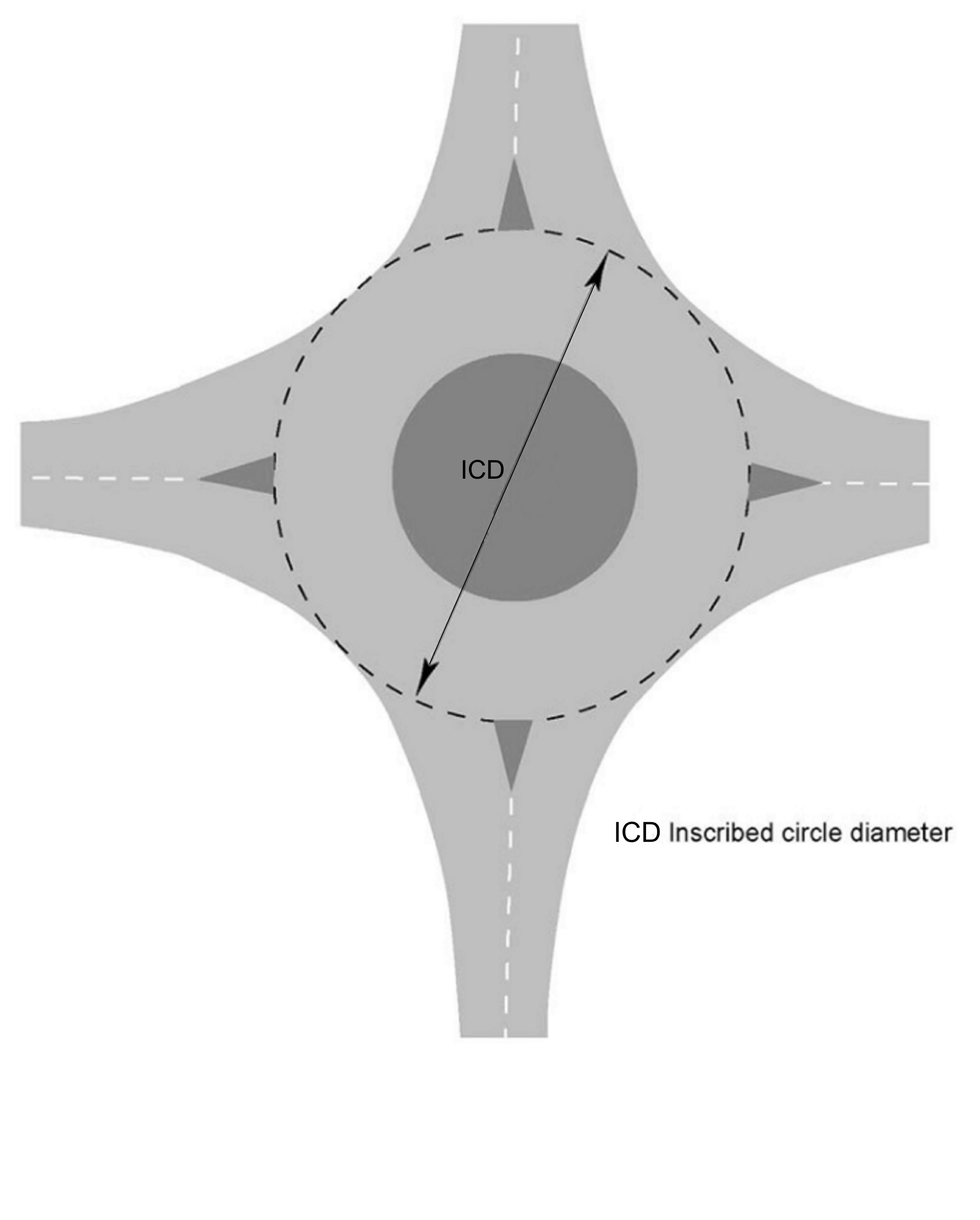
| Inscribed circle diameter (ICD) | the diameter of the largest circle that can be inscribed within the roundabout kerbs NOTE 1: The symbol for the ICD is D. |
| Intermediate give way line | a give way line at the end of the link between the two roundabouts, on a double roundabout |
| Intervisibility zone | at a signal-controlled roundabout, a zone identified for the purpose of assessing visibility within the junction between drivers at each stop line, or between drivers and pedestrians NOTE 1: The intervisiblility zone facilitates identification of measures to mitigate the effect of obstructions. |
| Lane bifurcation | one lane widening into two |
| Large roundabout | a roundabout with an ICD in excess of 100 metres NOTE 1: For design purposes, a large roundabout is classed as a normal roundabout. |
| Lateral shift | the alteration of the vehicle path to the side (laterally) NOTE 1: On the approach to a mini-roundabout, a lateral shift is used to create some deflection and is provided by the use of road markings. |
| Median line | the centre line (situated between the two opposing streams of traffic) on a single carriageway |
| Mini-roundabout | a roundabout where the central island is not kerbed, and with an ICD not exceeding 28 metres NOTE 1: A mini-roundabout has a flush or domed circular solid white road marking that is between 1 metre and 4 metres in diameter. |
| Near-side crossing | a crossing where the WCHR signal heads are located on the near-side, that is, on the side the WCHR is crossing from |
| Non-physical segregated left turn lane (SLTL) | a dedicated left turn lane from a roundabout entry to the first exit. Traffic is separated from the roundabout entry, circulatory carriageway and exit by means of a non-physical island delineated using road markings only. NOTE 1: This definition also applies to segregated lanes at three-arm and asymmetrically arranged roundabouts. |
| Non-physical subsidiary deflection island (SDI) | an island delineated by road markings alone, located between two entry lanes on the approach arm of a roundabout and shaped to direct, deflect and separate traffic movements onto the roundabout |
| Normal roundabout | a roundabout with a central island of at least 4 metres in diameter; and an ICD of between 28 metres and 100 metres NOTE 1: A normal roundabout can have dual or single carriageway approaches, and flared entries and exits to allow two or three vehicles to enter or leave the roundabout on a given arm at the same time. |
| Part-time control | the condition where signals are switched on at set times (generally peak periods) or under certain traffic conditions by queue detectors. When traffic flows are light the roundabout operates in a self-regulating manner under normal priority control. |
| Partial concentric markings | markings which vary from concentric markings in that their continuity around the circulatory carriageway is broken, usually adjacent to the entries and/or exits of the roundabout |
| Pedestrians / walkers | a person travelling by foot NOTE 1: The terms pedestrians and walkers are used interchangeably in this document. |
| Physical segregated left turn lane (SLTL) | a dedicated left turn lane from a roundabout entry to the first exit. Traffic is separated from the roundabout entry, circulatory carriageway and exit by means of a kerbed island and associated road markings. NOTE 1: This definition also applies to segregated lanes at three-arm and asymmetrically arranged roundabouts. |
| Physical subsidiary deflection island (SDI) | a raised kerbed island and associated road markings on the carriageway, located between two entry lanes on the approach arm of a roundabout and shaped to direct, deflect and separate traffic movements onto the roundabout. |
| Planting | this is vegetation, which includes grass, wildflowers, perennials, shrubs and trees |
| Reverse curve | a curve where two consecutive circular arcs curve in opposite directions and meet |
| Roundabouts | a junction with a one-way circulatory carriageway around a central island. Vehicles on the roundabout circulatory carriageway have priority over approaching vehicles. |
| Segregated lane | a lane from a roundabout entry to the first exit, separated from the roundabout entry, circulatory carriageway and exit by means of a kerbed island and associated road markings on a three-arm or asymmetrically arranged roundabout. |
| Signal-controlled roundabout | a roundabout with traffic signals on one or more of the approaches and at the corresponding point on the circulatory carriageway |
| Speed table | a raised platform to reduce traffic speeds |
| Spiral markings | a marking system involving a series of lane gains and lane drops around the circulatory carriageway so that drivers enter in the lane designated for their desired exit, and follow the lane around the roundabout to be led off at that exit NOTE 1: The width of a particular exit can determine how many circulating lanes lead off the roundabout. |
| Swept (turning) path | the path of different parts of a vehicle when that vehicle is undertaking a turning manoeuvre |
| Through-about | a signalised roundabout, which takes the major through-traffic movements from the circulatory carriageway, and routes them directly across the central island NOTE 1: Through-about junctions are also referred to as “hamburgers” and “fly-through roundabouts”. |
| Traffic deflection island | a raised kerbed island and associated road markings on the carriageway, located between an entry and exit on the same roundabout arm. NOTE 1: A traffic deflection island is shaped to direct and also separate opposing traffic movements onto and from a roundabout circulatory carriageway. |
| Traffic island | a raised (kerbed) or marked-off area on the road NOTE 1: A traffic island can be used to accommodate pedestrian refuges and traffic signals, and as a means of separating lanes of traffic or opposing traffic flows. |
| Uncontrolled crossing | a crossing that is not controlled by signals |
| Upstream | something moving or situated in the opposite direction from that in which traffic flows |
1. Scope
Aspects covered
1.1 This document shall be used for the geometric design of roundabouts, including signal-controlled roundabouts.
NOTE 1 This document is applicable to new and improved junctions on trunk roads.
NOTE 2 The geometric design of roundabouts covers:
- the selection of roundabouts;
- circulatory carriageway;
- central islands;
- traffic islands;
- entries and exits;
- visibility;
- differential acceleration lanes;
- segregated left turn lanes; and
- subsidiary deflection islands.
NOTE 3 Section 3 provides requirements and advice for all roundabout designs, including requirements and advice which are specific to normal and compact roundabouts (as indicated in specific clauses). Specific requirements and advice for the design of mini-roundabouts, signal-controlled roundabouts, segregated left-turn lanes, segregated lanes and subsidiary deflection islands are contained in their respective chapters.
1.2 Geometric design of the elements between the two points (the link upstream of the roundabout entry flare and the link downstream of the roundabout exit taper) shall be in accordance with the requirements of this document as illustrated in Figure 1.2, except for approach and exit stopping sight distance (SSD) visibility and differential acceleration lanes (DALs) design elements which have requirements that overlap the CD 109 and CD 116 thresholds shown in Figure 1.2.
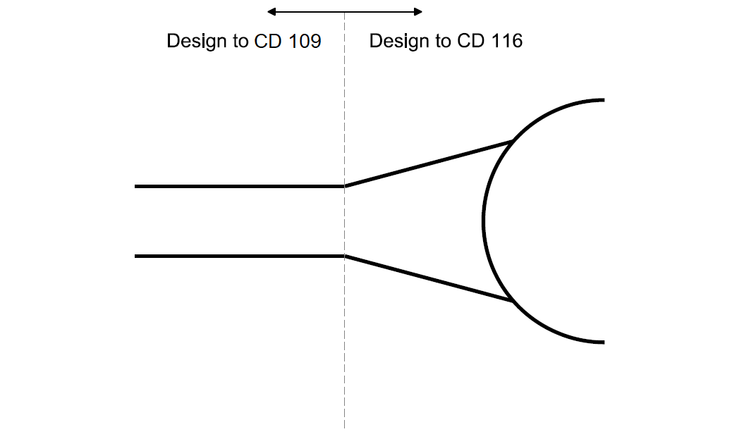
NOTE 1 Requirements for approach and exit stopping sight distance (SSD) visibility and differential acceleration lanes (DALs) are within Section 3, "Main geometric design features" and Section 4, "Additional requirements and advice for design of signal-controlled roundabouts''.
NOTE 2 Requirements and advice for immediate approach SSD visibility to roundabouts are given in CD 109 [Ref 4.N] in addition to this document.
1.3 All traffic signs and road markings must conform to the UKSI 2016/362 (TSRGD) [Ref 9.N] and amendments thereof.
NOTE 1 Overseeing Organisation specific requirements are provided in the National Application Annexes.
NOTE 2 DfT Circular 01/13 [Ref 11.I] gives guidance on setting speed limits at roundabouts and TSM Chapter 3 [Ref 12.N] gives guidance on the positioning of speed limit signs.
Implementation
1.4 This document shall be implemented forthwith on all schemes involving the geometric design of roundabouts on the Overseeing Organisations’ motorway and all-purpose trunk roads according to the implementation requirements of GG 101 [Ref 5.N].
Use of GG 101
1.5 The requirements contained in GG 101 [Ref 5.N] shall be followed in respect of activities covered by this document.
2. Roundabout types
General
2.1 At-grade roundabouts shall not be provided on motorways.
NOTE A roundabout designed as part of a grade separated junction follows the same requirements as a normal roundabout unless stated otherwise in this document.
2.1.1 On all-purpose trunk roads, roundabouts should not be located:
- on rural three-lane dual carriageway roads, as it is difficult to achieve suitable deflection;
- where an approach road exceeds a gradient of 2% over the desirable minimum stopping sight distance (SSD) measured from the give way or stop line.
2.1.2 A roundabout should have 3 or more arms.
NOTE 1 In addition to operating as a junction, a roundabout can also:
- facilitate changes in road standard (for example, between dual and single carriageways or grade separated and at-grade junction roads);
- emphasise the transition between rural and urban environments;
- allow U-turns;
- facilitate heavy right turn flows;
- mitigate against the inconvenience of nearby banned right turns; and,
- bring a route through a sharp or sudden change of direction.
NOTE 2 In providing a roundabout, combinations of the following factors are known to result in load shedding:
- long straight high speed approach or circulatory of the roundabout;
- inadequate entry deflection;
- low circulating flow combined with excessive visibility to the right;
- significant tightening of the turn radius partway round the roundabout;
- excessive crossfall changes on the circulatory carriageway or the exit;
- excessive outward sloping crossfall on a nearside lane of the circulatory carriageway; and,
- excessive entry deflection.
NOTE 3 Roundabouts can include additional design features, such as segregated left turn lanes (SLTL), subsidiary deflection islands (SDI) and differential acceleration lanes (DAL) where these can assist the smooth flow of traffic through the junction.
NOTE 4 Designing roundabouts to the requirements and advice provided within this document can help reduce risks of accidents involving powered two-wheelers (PTWs). The IHE Guidelines for Motorcycling IHE GfM [Ref 5.I] provides guidance on PTW issues.
2.1.3 On single carriageway roads, roundabouts may:
- be sited to optimise the length of straight overtaking sections; and,
- provide an overtaking opportunity by having a short length of two lanes on the exit arms of the roundabout.
2.1.4 Roundabouts should be made conspicuous through the provision of clear signage and road markings.
NOTE 1 Guidance on signage and road markings for roundabouts is provided in TSM Chapter 3 [Ref 12.N](Regulatory Signs), TSM Chapter 4 [Ref 13.N](Warning Signs), TSM Chapter 5 [Ref 14.N](Road Markings) and TSM Chapter 7 [Ref 16.N](Design of Traffic Signs).
NOTE 2 The following measures can help improve conspicuousness of roundabouts:
- repositioning and/or repeating (e.g. nearside and offside) of warning signs;
- providing additional map type direction signs in advance of the roundabout, possible sign configurations include:
-
- 3 lane dual-carriageway (50, 60 or 70mph) - 1 mile ADS, 1/2 mile ADS and final direction sign and warning signs (3 lane dual-carriageway approaches to a roundabout are not preferred);
- 2 lane dual-carriageway (60 or 70mph) - 1 mile ADS (optional - site specific road safety issue / high traffic volume), 1/2 mile ADS and final direction sign and warning signs; or
- any dual carriageway (lower than 50mph) - final direction sign and, if considered necessary, one pair of warning signs;
- making the give way line more conspicuous;
- extending the central island chevron sign further to the left to emphasise the angle of turn;
- extending the central island chevron sign further to the right or providing additional chevrons on the approach central island where the approach geometry masks the roundabout entry from view; and/or,
- on dual carriageway roads, placing additional chevron signs in the central reserve in line with the offside lane approach.
NOTE 3 Allowable positioning of chevrons is dependent on the 85th percentile approach speeds, visibility distance and guidance provided in UKSI 2016/362 (TSRGD) [Ref 9.N] and TSM Chapter 4 [Ref 13.N].
2.2 Road lighting shall be provided on all roundabouts.
NOTE Overseeing Organisation specific requirements related to roundabouts are provided in the National Application Annex.
Normal and compact roundabouts
2.3 For roads with a speed limit of 50 mph or greater and traffic levels of greater than 8,000 two-way AADT on any approach, a normal roundabout shall be used.
2.3.1 Where the speed limit is 50 mph or greater regardless of traffic flow, normal roundabouts should be provided.
2.3.2 Where the speed limit is 50 mph or greater, and traffic levels are less than 8,000 two-way AADT on any approach and where single lane entries are provided, compact roundabouts may be provided.
2.3.3 For roads with a posted speed limit of 40 mph or below, either a compact or a normal roundabout may be provided.
NOTE 1 On roads with speed limits exceeding 40 mph, the design of compact roundabouts is similar to that for normal roundabouts, but single-lane entries and exits are provided.
NOTE 2 Where the posted speed limit is 40 mph or less, compact roundabouts are recommended for traffic levels of less than 8,000 two-way AADT on all approaches and normal roundabouts are recommended for traffic levels of greater than 12,000 two-way AADT on any approach.
NOTE 3 Alternatives to normal or compact roundabout types (i.e., signalised, double, through-about and double-through-about, mini, or provision of an SLTL) can be used where the traffic modelling indicates a benefit.
NOTE 4 Where the design of a normal roundabout could lead to high circulatory speeds then a double roundabout or signalisation can be used to reduce speeds and to regulate traffic flow.
NOTE 5 Where visibility to the right cannot be achieved at normal roundabouts, signal-control can mitigate this problem due to application of alternative visibility requirements.
NOTE 6 New roundabouts positioned off-line from the existing link can result in approaching road users looking past the roundabout central island, creating a 'see-through' effect which could increase collision risk. Signing and lining, and physical cues located on approach and on the central island, help drivers interpret the layout of new off-line roundabouts.
2.3.4 Normal roundabouts with five or more arms should not be provided.
NOTE 1 At a roundabout, the accident risk is likely to increase with the number of entries provided (based on a research study between 1999 and 2003; a summary of this provided in TRL PPR 206 [Ref 2.I]).
NOTE 2 The number of arms on a roundabout is linked to the ICD of the roundabout - the more arms, the larger the ICD. Larger ICDs can encourage higher circulatory speeds.
2.4 Compact roundabouts shall not be used at any location with a dual carriageway approach, irrespective of speed or AADT.
NOTE 1 A compact roundabout has less capacity than a normal roundabout but can be more suitable where there is a need to accommodate at-grade crossings for pedestrians or cyclists.
NOTE 2 Non-flared entries/exits of a compact roundabout give more flexibility for the inclusion of pedestrian crossings in the roundabout design.
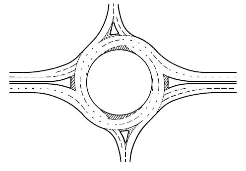
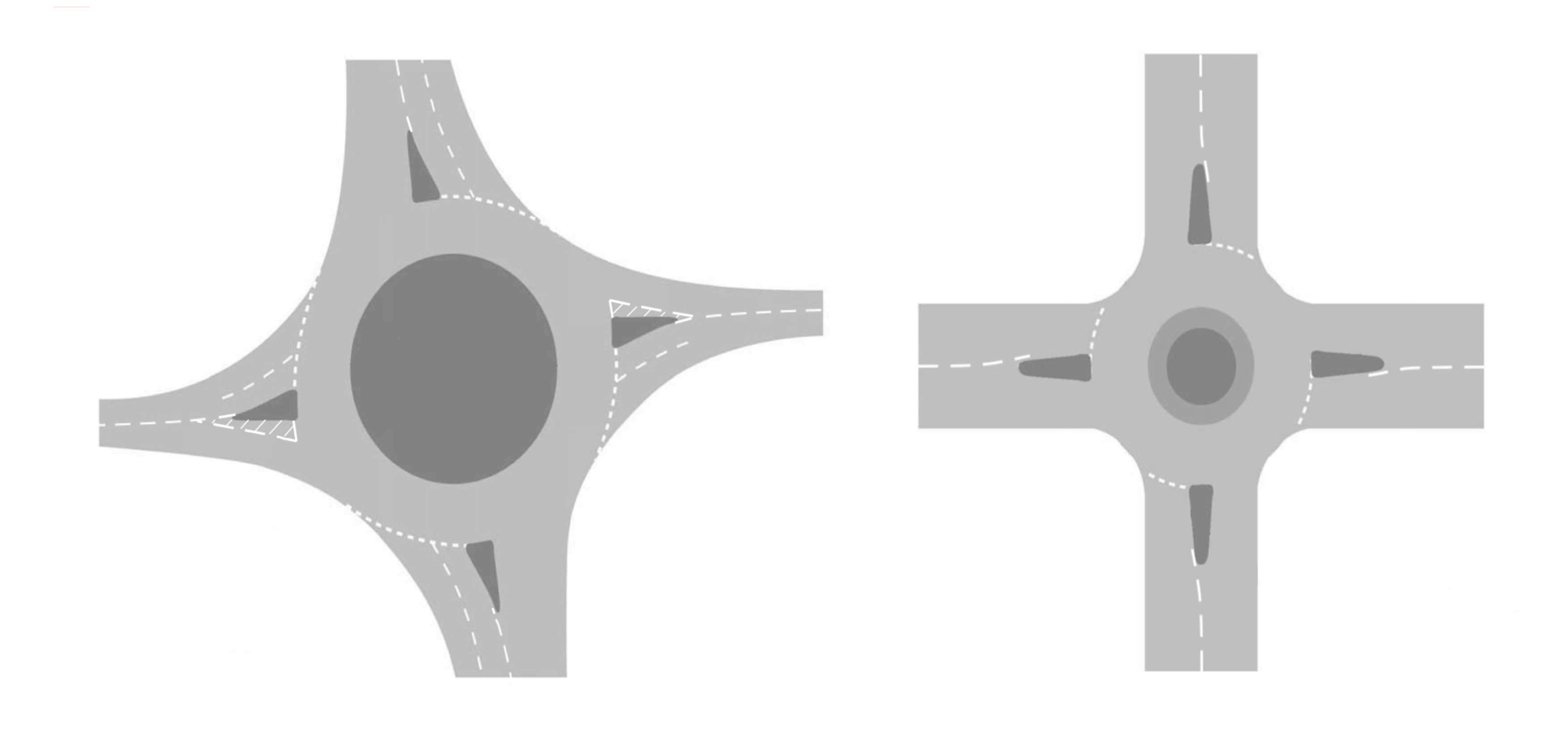
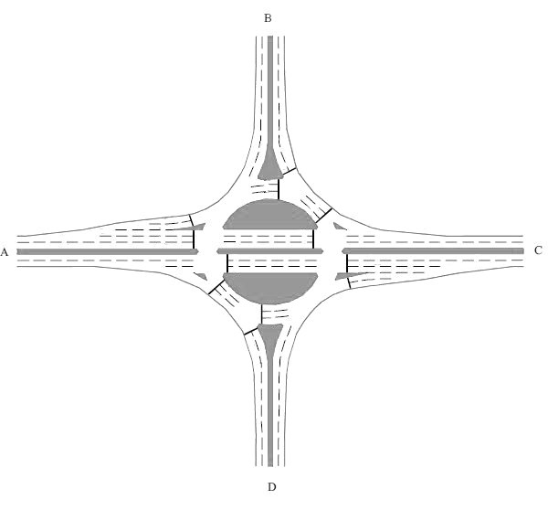
NOTE 3 Normal and compact roundabouts are as illustrated in Figure 2.4N3.
Signal-controlled roundabouts
2.5 Signal-controlled roundabouts shall be designed using the requirements for a normal roundabout unless stated otherwise in this document.
NOTE 1 General requirements and advice for signal-controlled junctions, including positioning of and visibility to signals, that are applicable to roundabouts and other junctions, are provided in Section 4 and CD 123 [Ref 3.N].
NOTE 2 Signal-controlled roundabouts include roundabouts which operate using direct signal-control or indirect signal-control.
2.6 Where a signal-controlled roundabout is designed using the requirements for a normal roundabout, the give way line reference for a normal roundabout shall be the stop line for a signal-controlled roundabout.
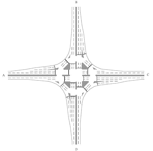
2.7 Direct signal-controlled roundabouts (as illustrated in Figure 2.7) shall have traffic signal-control (part-time or full-time) on one or more of the approaches and at the corresponding point on the circulatory carriageway.
NOTE Signal-controlled roundabouts include traffic signal-controlled gyratory systems that are not always a conventional (circular) roundabout shape.
2.7.1 When the traffic on a roundabout does not self-regulate, direct or indirect traffic signals may need to be installed either part-time or continuous at some or all of the entry points.
NOTE Where traffic on a roundabout does not self-regulate, this can be caused by:
- an overall growth in traffic flow;
- an overloading or an unbalanced flow at one or more entries;
- high circulatory speeds; and/or
- disparity of traffic flow patterns between peak and off-peak periods.
Through-abouts
2.8 Traffic signal-control shall be used on the through route conflict points on a through-about (as illustrated in Figure 2.8a) or double-through-about (as illustrated in Figure 2.8b).
NOTE 1 Traffic signal-control on the through route conflict points on a through-about or double-through-about is the minimum requirement, additional signal-control can be added.
NOTE 2 A through-about junction is less efficient in handling turning movements than a roundabout.
NOTE 3 The benefit of a through-about junction is that major traffic movements are removed from some of the conflicts on the circulatory carriageway and this can provide increased capacity.
NOTE 4 A double-through-about is useful if the dominant flows are the two straight ahead movements, reducing conflict on the circulatory carriageway.
NOTE 5 Through routes on a through-about can have signal-controlled junction, highway link and roundabout design elements, as well as advanced signal technology, installed to control approach speeds and optimise capacity. Therefore, an ‘aspect not covered’ departure is necessary to be submitted to the Overseeing Organisation for any proposed through route so that all design elements can be considered holistically.
2.8.1 Through-about and double-through-about junctions should have clear directional signage, that includes directions that right turning traffic needs to be in the left-hand lane.
NOTE 1 Map type signing helps illustrate correct routing through through-about junctions.
NOTE 2 Map type signing for a through-about junction necessitates non-prescribed sign authorisation by the relevant national authority. Information regarding this process can be obtained from the Overseeing Organisation.
Mini-roundabouts
2.9 Mini-roundabouts shall only be used on roads with a speed limit of 30 mph or less and where the 85th percentile speed of traffic is less than 35 mph within a distance of 70 metres from the proposed give way line on all approaches.
NOTE 1 Traffic calming measures on the approach to a mini-roundabout can be used to reduce 85th percentile speeds to below 35 mph. Advice on speed reduction measures can be found in TAL 2/05 [Ref 17.I], LTN 1/07 [Ref 9.I], UKSI 1999/1026 [Ref 8.N], and UKSI 1999/1025 [Ref 14.I].
NOTE 2 Mini-roundabouts can be inappropriate for use on routes frequently used by HGVs and buses due to difficulty in completing turning manoeuvres.
NOTE 3 Mini-roundabouts are not suitable where large volumes of cyclists, motorcyclists, or inexperienced cyclists (on routes to schools for example) are likely to use them except in conjunction with speed reduction measures.
2.10 Mini-roundabouts (as illustrated in Figure 2.10) shall not be used at:
- new junctions;
- accesses linking directly to a site that serve, or are intended to serve, one or more properties; nor,
- on dual carriageways.
2.10.1 Mini-roundabouts should not be installed where traffic flows or turning proportions differ significantly between arms.
NOTE When traffic flows are low, drivers can not anticipate conflict with other road users which can result in them approaching the junction at inappropriate speeds. Inadequate or excessive visibility can exacerbate this situation.
2.10.2 Mini-roundabouts should not be used where there is a risk that vehicles will use them to perform U-turns.
NOTE Where provided adjacent to prohibited turning movements at other junctions, there is a risk that drivers use the mini-roundabout for U-turns.
2.10.3 The introduction of a mini-roundabout should be assessed to check that queues created by the mini-roundabout do not adversely impact upon the operation and safety of the junction or adjoining network.
2.11 Mini-roundabouts shall only have 3 or 4 arms.
2.12 A 3-arm mini-roundabout shall not be used where the predicted two-way annual average daily traffic flow (AADT) on any arm of a junction is below 500 vehicles a day.
2.13 A 4-arm mini-roundabout shall not be used where the predicted two-way annual average daily traffic flow (AADT) on any arm of a junction is below 500 vehicles a day unless the design incorporates features to encourage vehicles to give way on all approaches.
NOTE Four-arm mini-roundabouts introduce additional conflicts and can create difficulty for drivers’ perceptions of the layout and turning flows.
2.13.1 A 4-arm mini-roundabout should not be used where the sum of the maximum peak hour entry flows for all arms exceeds 500 vehicles per hour.
Double roundabouts
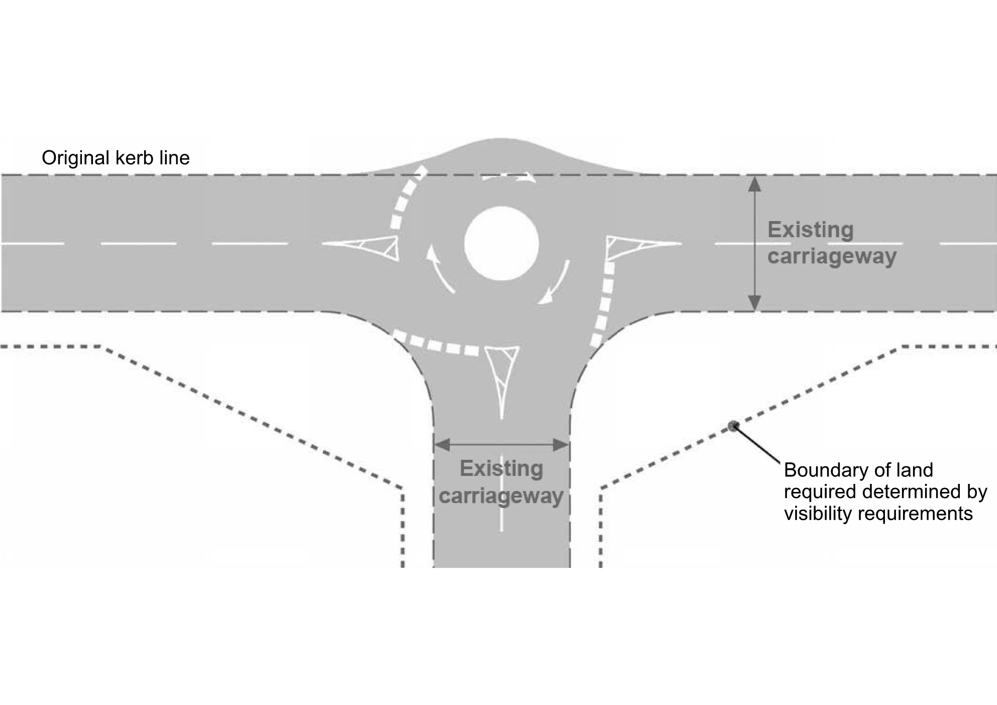
2.14 A double roundabout (as illustrated in Figure 2.14) shall not be designed as two independent roundabouts.
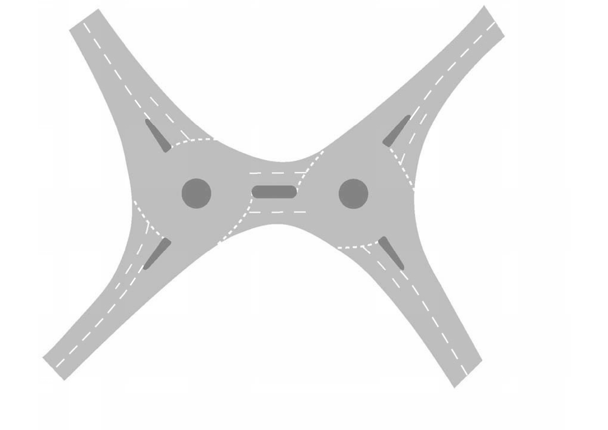
NOTE 1 A double roundabout can comprise two normal, compact or mini-roundabouts.
NOTE 2 Double roundabouts can be used:
- to improve an existing staggered junction (since they avoid the need to realign one of the approach roads and can be less expensive to construct than larger single island roundabouts);
- for joining two parallel routes separated by a feature such as a river, a railway line or a motorway;
- at overloaded single roundabouts where, by reducing the circulating flow past critical entries, they increase capacity;
- at junctions with more than four entries (since they can achieve increased capacity and improved safety with a more efficient use of the space, compared to a large roundabout which could generate high circulatory speeds, reducing the capacity and safety).
NOTE 3 Double mini-roundabouts separated by a short link can be used to improve traffic flows by replacing:
- a pair of closely spaced or staggered junctions; or
- an existing normal roundabout.
2.14.1 On a double roundabout, the lane use (based on the turning volumes) on the link between the two roundabouts should be balanced.
NOTE Often the link between the two roundabouts does not provide distance to change lanes. Reducing entry capacity on entries that feed the link can prevent traffic blocking back onto the roundabouts, increasing the overall capacity.
3. Main geometric design features
Inscribed circle diameter
3.1 The inscribed circle diameter (ICD) of a roundabout shall be the diameter of the largest circle that can be inscribed within the junction kerbs.
3.2 The ICD for a circular roundabout shall be measured as shown in Figure 3.2.
3.3 Where the outline of the roundabout is non-circular, two times the radius at the respective entry shall be used to calculate the corresponding ICDs, as shown in Figure 3.3.
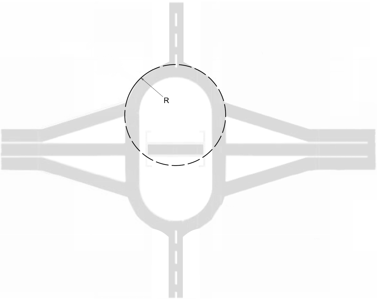
NOTE Where the outline of the roundabout is non-circular, the ICD at each entry is calculated separately.
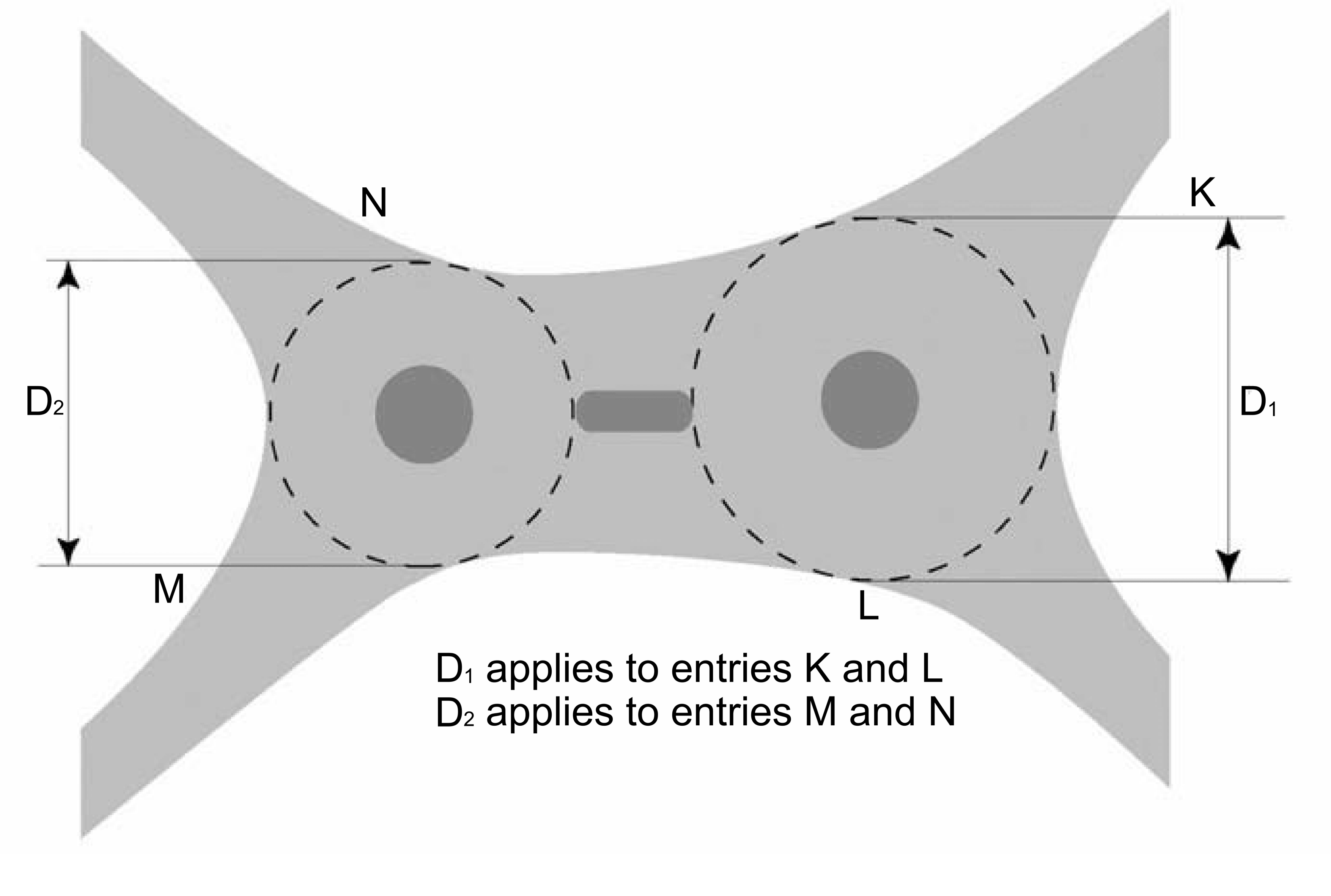
3.4 The ICDs for a double roundabout shall be measured as shown in Figure 3.4.
3.5 The minimum value of the ICD for a normal or compact roundabout shall be 28 metres; this is the smallest roundabout that can accommodate the swept path of the design vehicle.
3.5.1 The ICD of a compact roundabout should not exceed 36 metres.
3.5.2 The ICD of a normal roundabout should not exceed 100 metres.
NOTE 1 Large ICD can lead to excessive vehicle speeds on the circulatory carriageway.
NOTE 2 More than one roundabout can be used to mitigate against an ICD exceeding 100 metres.
Circulatory carriageway
3.6 The width of the circulatory carriageway for normal or compact roundabouts shall be between 1.0 and 1.2 times the maximum entry width, excluding any overrun area.
NOTE The entry width is shown on Figure 3.11.
3.6.1 The circulatory carriageway of normal or compact roundabouts should be circular and of constant width.
NOTE 1 Roundabouts can be non circular due to staggered road arrangements, land constraints, to allow for dominant mainline flow capacity, and/or to cater for associated structures and slip road layouts for grade separated junctions.
NOTE 2 Varying widths of circulatory carriageways can be used to optimise safety and capacity at roundabouts where traffic flows differ widely between arms.
NOTE 3 Advice on designing road markings on the circulatory carriageway and approaches is provided in Appendix D.
3.6.2 Dedicated lane signs and road markings may be used on the circulatory carriageway where appropriate.
3.6.3 Gantry mounted signs may be used on wide approaches to a roundabout or circulatory carriageway, where tall vehicles could obscure post mounted signs.
NOTE Further guidance on the provision of gantry mounted signs is provided in CD 146 [Ref 6.N].
3.6.4 Where the turning proportions are such that one section of the circulatory carriageway has a relatively low flow, resulting in an unused area of carriageway, the circulatory carriageway should be reduced in width.
NOTE Where the circulatory carriageway in one section needs to be reduced in width, the reduced width can be achieved by extending the traffic island, or by increasing the size of the central island. This includes providing appropriate road markings to guide road users past any extended kerb lines.
3.6.5 At normal roundabouts the width of the circulatory carriageway should not exceed 15 metres.
3.6.6 The width of the circulatory carriageway on a normal roundabout should accommodate the number of lanes provided on entries and exits.
3.6.7 At compact roundabouts, the width of the circulatory carriageway should not exceed 6 metres, so that it is not possible for two cars to pass one another.
3.6.8 On the circulatory carriageway, short lengths of reverse curve should be avoided between entry and adjacent exits.
NOTE 1 Short lengths of reverse curves can be avoided:
- by linking the curves with a short straight section;
- by reducing the size of the ICD; or
- by converting to a double roundabout.
NOTE 2 Where there is a considerable distance between the entry and the next exit, such as at three-arm roundabouts, reverse curvature is acceptable (see Figure 3.6.8N2).
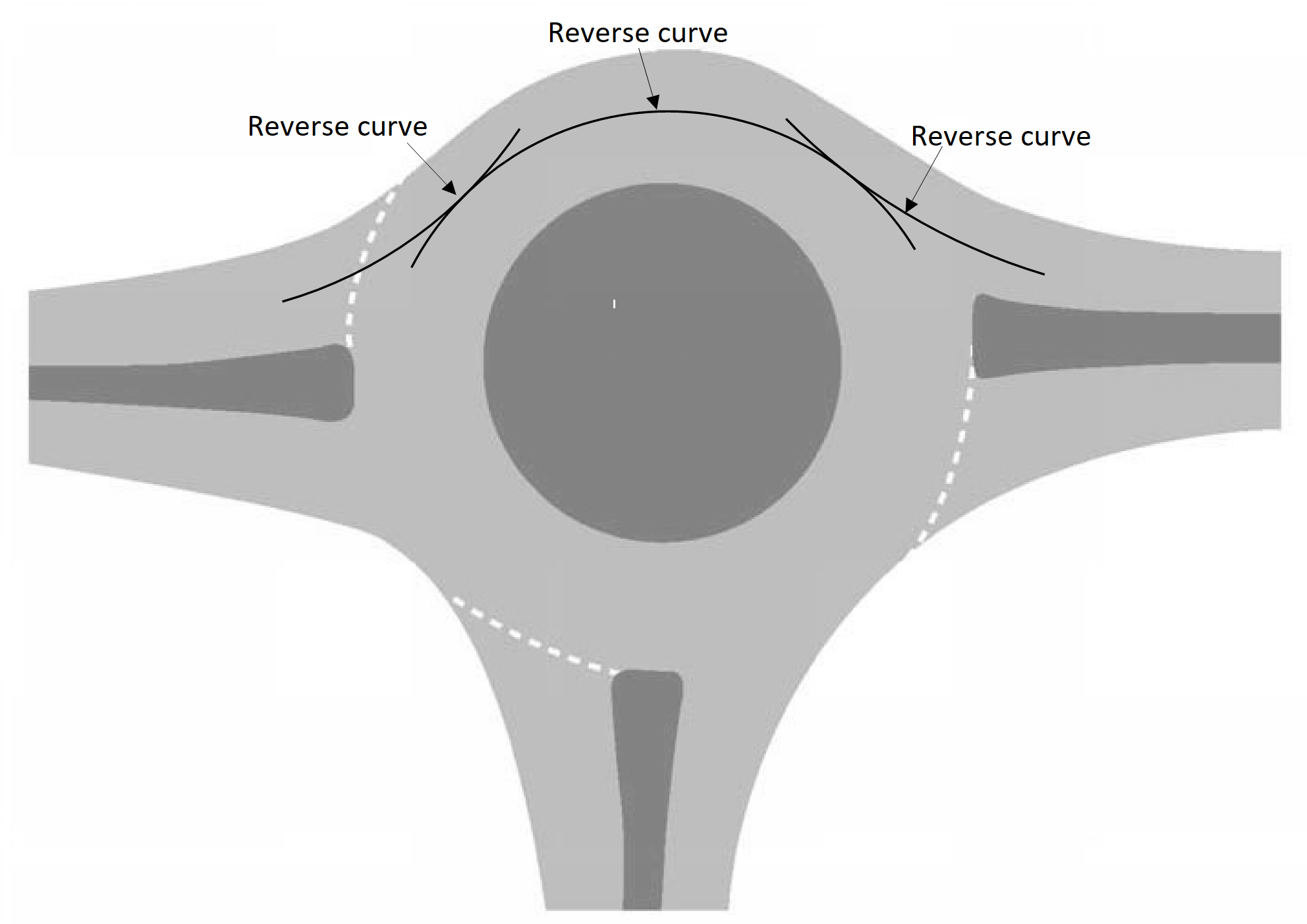
NOTE 3 Reverse curves (to the right and then to the left on the approach) can be effective in providing additional deflection on poorly aligned existing roundabouts, but sharp curves are not good practice and could induce HGV rollover or accidents involving powered two wheelers (PTW).
3.6.9 The circulatory carriageway lane markings should be designed to:
- create smooth paths around the junction for all movements;
- maximise the use of the circulatory carriageway width wherever possible;
- provide a smooth link between any entry and exit markings to guide drivers safely around the junction; and,
- allow sufficient swept path of the largest vehicle anticipated to use each individual lane (for non-signal-controlled roundabouts).
NOTE 1 Advice on designing road markings on the circulatory carriageway is provided in Appendix D.
NOTE 2 Research has shown that an articulated HGV with a centre of gravity height of 2.5 metres above the ground can overturn on a 20 metre radius bend at speeds as low as 15 mph (24 kph). See TRL LR 788 [Ref 1.I].
3.6.10 The circulatory markings should be positioned so that the circulating lanes are visible from each entry to offer drivers a clearly defined position on the circulatory carriageway to which to direct their vehicle, thereby reducing potential conflict.
3.6.11 Lane direction arrows may be used on the circulatory carriageway.
3.6.12 Lane direction arrows should be visible to both entering and circulating drivers.
3.6.13 To facilitate better driver perception on the circulating carriageway, “straight ahead” and “right” arrows may be used to denote lanes that continue to circulate.
NOTE 1 Driver’s perception of what is represented by “left”, “straight ahead” and “right” arrows is less clear when circulating, further guidance on the use of direction arrows is provided in TSM Chapter 5 [Ref 14.N].
NOTE 2 Further guidance is provided in Section 3, "Lane direction markings".
3.6.14 Lane direction arrows denoting a left turn immediately prior to an exit may be utilised and prove beneficial to signify that a lane drop around the circulatory carriageway is approaching.
NOTE 1 The use of road markings can be beneficial in reducing three types of accident at roundabouts:
- side-to-side collisions on the circulatory carriageway;
- drivers being forced onto the central island; and
- collisions between entering and circulating vehicles.
NOTE 2 Road markings can help reduce accidents by guiding drivers; on the approach, onto and around the circulatory carriageway. This in turn reduces weaving on the circulatory carriageway and can reduce the uncertainty experienced by a driver at the give way line as to the path and destination of circulating vehicles, particularly at larger roundabouts.
NOTE 3 On roundabouts where flow patterns have changed since design, road markings can help to:
- improve throughput at high levels of traffic flow;
- cater for particularly high turning movements;
- smooth the flow at roundabouts with irregular geometry; and,
- improve safety.
3.6.15 The use of route numbers and/or destinations can also assist drivers’ understanding, although their use should not clutter the circulatory carriageway or make the markings unduly confusing, as could happen where destinations are seen to change between circulatory lanes.
3.6.16 Spiral markings should be provided on larger diameter normal roundabouts where the number of circulating lanes is to be varied to aid general operation.
3.6.17 Spiral markings and vehicle paths through roundabouts should:
- follow smooth flowing alignments;
- have gradually increasing radius; and
- avoid reducing radius.
NOTE Further guidance on spiral markings is provided in Appendix D.
3.6.18 Spiral marking radii should be gradual to avoid:
- increasing the likelihood of load shedding by HGV; or,
- causing loss of control accidents (particularly for PTW).
NOTE Spiral markings can improve lane discipline on the circulatory carriageway. Designation of lanes on the approach can also help.
Central island
3.7 The central island of normal and compact roundabouts shall be at least 4 metres in diameter.
3.7.1 The central island of normal and compact roundabouts should be circular.
NOTE 1 The central island can be non-circular due to staggered road arrangements, land constraints, to allow for dominant mainline flow capacity, and/or to cater for associated structures and slip road layouts for grade separated junctions.
NOTE 2 At grade separated junctions, the layout of the slip roads and associated structures can influence the shape of the central island.
3.7.2 The central island of normal and compact roundabouts should be kerbed.
3.7.3 The carriageway edges of a through route within a through-about should be kerbed.
3.7.4 To achieve circulatory visibility requirements, the use of planting on roundabouts within central islands of 10 metres or less should be avoided.
NOTE As long as visibility is not restricted, planting on central islands less than 1 metre in height can help to mitigate against any see through effect, which can result in failure to give way, particularly on roundabouts with downhill approaches.
3.7.5 Solid features such as statues, trees or rocks should not be placed on the central islands of roundabouts with high speed approaches, or anywhere within the highway boundary adjacent to the roundabout where there is a high risk of collision.
3.7.6 Non-passive infrastructure and landscaping may be located on the central island of urban roundabouts where there is sufficient space to do so and there are low speed approaches on all arms.
NOTE 1 Central islands with diameters greater than 35 metres can provide sufficient space for the provision of non-passive infrastructure or landscaping on urban roundabouts.
NOTE 2 Further requirements and advice for the landscape design of the central island are provided in LD 117 [Ref 8.I].
Overrun areas
3.8 A roundabout shall provide space for the turning movements of the design vehicle in accordance with Table 3.8.
| Central island diameter (metres) | R1 (metres) | R2 (metres) | Minimum ICD (metres) |
| 4.0 | 3.0 | 13.0 | 28.0 |
| 6.0 | 4.0 | 13.4 | 28.8 |
| 8.0 | 5.0 | 13.9 | 29.8 |
| 10.0 | 6.0 | 14.4 | 30.8 |
| 12.0 | 7.0 | 15.0 | 32.0 |
| 14.0 | 8.0 | 15.6 | 33.2 |
| 16.0 | 9.0 | 16.3 | 34.6 |
| 18.0 | 10.0 | 17.0 | 36.0 |
NOTE The design vehicle for Table 3.8 and Figure 3.8.1N1 is an articulated vehicle with a single axle at the rear of the trailer, of length 15.5 metres.
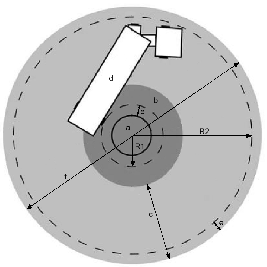
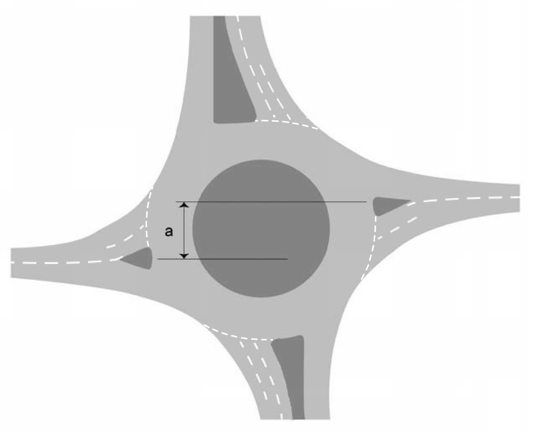
3.8.1 An overrun area may be necessary (Figure 3.8.1N1) to provide sufficient entry deflection for vehicles at compact or smaller normal roundabouts while still allowing large vehicles to circulate.
NOTE 1 An overrun area for a compact or smaller normal roundabout is illustrated in Figure 3.8.1N1, where:
- a, is the main central island;
- b, is the central overrun area (where provided);
- c, is the remaining circulatory carriageway width (1.0 to 1.2 times the maximum entry width);
- d, is the vehicle;
- e, is the 1 metre minimum clearance from the edge of kerbing (provided on both the inside and the outside of the circulatory carriageway);
- f, is the ICD;
- R1, is the radius from the centre of the roundabout to the outside of the inner 1 metre clearance (e) (values for R1 can be found in Table 3.8.1N1); and
- R2, is the radius from the centre of the roundabout to the inside of the outer 1 metre clearance (e) (values for R2 can be found in Table 3.8.1N1).
NOTE 2 In urban areas, providing adequate turning space for long vehicles can be an important consideration.
3.8.2 The swept path for the design vehicle for Figure 3.8.1N1 may impinge by up to 0.3 metres into either the inner or outer 1-metre clearance allowance ('e', as shown on Figure 3.8.1N1) of the central island where there are constraints.
NOTE Given the anticipated low frequency of the design vehicle for Figure 3.8.1N1, the impingement into the inner and outer clearance is not particularly significant and the dimensions in Table 3.8 need not be increased accordingly.
3.9 The profile dimensions for an overrun area must be in accordance with The Highways (Traffic Calming) Regulations UKSI 1999/1026 [Ref 8.N].
NOTE Advice on the use of overrun areas is provided in TAL 12/93 [Ref 10.N].
3.9.1 The compact and normal roundabout overrun area should be capable of being mounted by the trailers of a HGV, but be unattractive to cars e.g. by having a slope and/or a textured surface.
3.9.2 Overrun areas should not be used adjacent to walkers, cyclists and horse-riders (WCHR) crossings.
NOTE WCHR waiting within an overrun area puts them at risk of being struck by passing vehicles.
3.9.3 Where an overrun area is used adjacent to a pedestrian crossing, the overrun areas should not resemble footways or refuges in order to discourage pedestrians utilising it to cross the carriageway.
Traffic islands
3.10 Traffic islands shall be used on each arm of a normal or compact roundabout, located and shaped so as to separate and direct traffic entering and leaving the roundabout.
NOTE On dual carriageway approaches to roundabouts, the central reserve acts as a traffic island separating opposing traffic flows.
3.10.1 Traffic islands should be kerbed physical islands.
NOTE Kerbed traffic islands can act as WCHR refuges.
3.10.2 Signs and other street furniture which are sited on kerbed islands should be located so as not to interfere with visibility.
3.10.3 Where there is insufficient space to accommodate a kerbed island, traffic islands may consist entirely of markings.
3.10.4 Extensions of traffic islands should be by physical means, such as by kerbing, and not by hatching or road markings.
NOTE The reduction of excessive entry width by extending the traffic island can help reduce accident risks at some roundabouts.
3.10.5 Road markings may be used to extend a traffic island on the roundabout approach, the exit or on the circulatory carriageway where the existing carriageway requires narrowing and provision of a kerbed island is not possible.
NOTE Advice on the provision and design of road markings is provided in Appendix D.
3.10.6 Planting on a dual carriageway approach central reserve or traffic island should not be placed within 15 metres of the give way line.
NOTE 1 As long as visibility is not restricted, planting on central reserves or traffic islands can reduce the likelihood of drivers being distracted or confused by traffic movements on the opposite side of the roundabout.
NOTE 2 Providing planting on a dual carriageway approach central reserve or traffic island can increase safety risks to workforce, possibly increase costs to maintain the central reserve or traffic island and can create traffic management issues.
Entries
Entry width
3.11 The entry width shall be measured from point A at the right-hand end of the give way line along the normal to the nearside kerb where there are no road markings or hatching alongside the kerbs, as shown in Figure 3.11.

NOTE 1 The entry width is the width of the carriageway at the point of entry.
NOTE 2 For capacity assessment, the measurement is taken as the total width of the lanes which drivers are likely to use.
NOTE 3 Entry width and sharpness of flare are the most important determinants of capacity, whereas entry deflection is the most important factor for safety as it governs the speed of vehicles through the roundabout.
NOTE 4 Advice on calculating the capacity of the roundabout is provided in Appendix B.
3.11.1 Where there is white edge lining or hatching the measurement should be taken between the edges of the markings closest to the running lanes rather than kerb to kerb.
3.12 On a single carriageway approach to a normal roundabout, the entry width shall not exceed 10.5 metres.
3.12.1 On a single-carriageway road, where predicted flows are low and increased lane width is not operationally necessary, a compact roundabout with single lane entries should be used.
NOTE The use of single lane entries can result in entry closures during planned maintenance and therefore be subject to an agreed traffic management plan with the Overseeing Organisation.
3.13 On a dual carriageway approach to a normal roundabout, the entry width shall not exceed 15 metres.
3.14 Lane widths at the give way line for normal and compact roundabouts shall be no less than 3 metres and no greater than 4.5 metres.
3.14.1 At the give way line, a lane width value of 4.5 metres should be used at single lane entries.
3.14.2 At the give way line, lane width values of between 3 metres and 3.5 metres should be used at multi-lane entries.
NOTE The use of lane bifurcation where one lane widens into two can maximise the use of the entry width and can reduce the impact of drivers having a tendency to use the nearside lane when entering roundabouts.
3.14.3 Vehicle swept paths should be assessed using the largest vehicle that is anticipated to use each entry lane.
3.14.4 Vehicle swept paths should be assessed on multi-lane entries to ensure sufficient width is provided for each entry lane.
3.14.5 No more than two lanes should be added to the number of upstream lanes on the entry to a roundabout.
3.14.6 No entry should be more than four lanes wide.
3.14.7 Where entry flaring is provided, lane markings indicating the tapered lanes should start from a point where both lanes have a minimum width of 3 metres.
3.14.8 Where an existing approach arm is being modified and heavy goods vehicles and bus usage is infrequent, the minimum width of the lanes at the start of the tapered lanes at entry flaring may be reduced to 2.5 metres.
NOTE The choice of minimum width influences the length of segregated lanes on the approach to the roundabout and this can potentially impact the operational performance of the approach arm at peak times.
3.14.9 When developing additional entry lanes, short offside lanes should not be used.
NOTE Road users tend to infrequently use short offside lanes. This can result in debris collecting on the road surface, which forms a safety hazard, particularly for two-wheeled vehicles.
3.15 Hatching on the entry to reduce the entry width shall not be used in the controlled area of a zebra or signal-controlled crossing.
3.15.1 Hatching should not be used to reduce the entry width in areas adjacent to pedestrian crossing points.
Approach half width
3.16 The approach half width shall be measured as the width of the approach carriageway, excluding any hatching, in advance of any entry flare, as shown in Figure 3.16.
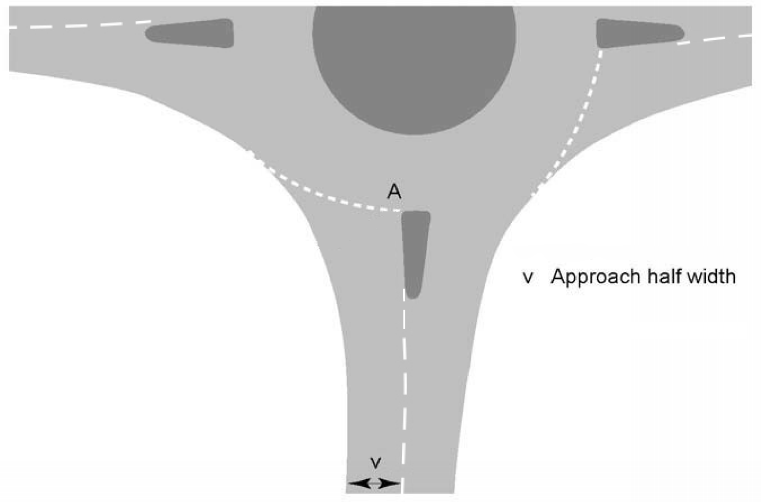
NOTE The approach half width is the shortest distance between the median line, or the edge of the central reserve on dual carriageway roads, and the nearside edge of the road.
3.16.1 Where there is white edge lining or hatching, the measurement of approach half width should be taken between markings rather than kerb to kerb.
Flaring
3.17 Entry flaring shall be measured using the average effective flare length, l' as shown on Figure 3.17.
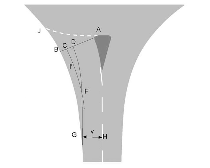
NOTE 1 The average effective flare length, l', is the average length over which the entry widens, and is the length of the curve CF'.
NOTE 2 Normal roundabouts usually have flared entries to accommodate one or two additional lanes at the give way line to increase capacity.
NOTE 3 The average effective flare length, l' (as illustrated in Figure 3.17) is determined following the below methodology:
- construct lines AB and GH;
-
- AB is e the entry width;
- and GH illustrates the approach half width, at a point G which is the best estimate of the start of the flare;
- construct curve GD parallel to the median HA (centre line or edge of central reserve or traffic island), maintaining a distance between the two lines equivalent the approach width, v;
- where AB is perpendicular to the median HA, the length of AD is to match the approach half width,v (line GH);
- where AB is not perpendicular to the median HA, the length of AD varies slightly from the approach half width. D is to be situated at the point where the line (GD) parallel to the median cuts the entry width,e, (line AB);
- curve BG is formed by the design kerb line;
- construct curve CF' parallel to curve BG (the nearside kerb) and at a constant distance of ½ BD from BG, with F' being the point where CF' intersects line GD;
- the length of curve CF' is the average effective flare length, l'.
NOTE 4 The total length of the entry widening (BG) can be about twice the average effective flare length, l'.
NOTE 5 The approach outlined in 3.17 follows that used in TRL LR 942 [Ref 15.I].
3.17.1 A minimum average effective flare length of 5 metres in urban areas and 25 metres in rural areas should be used, but capacity can be the determining factor for the actual length.
NOTE 1 Average effective flare lengths greater than 25 metres can improve the geometric layout but have little effect in increasing capacity.
NOTE 2 Where the average effective flare length exceeds 100 metres, the design becomes one of link widening. Requirements and advice for link design are provided in CD 109 [Ref 4.N].
NOTE 3 Single-lane entries e.g. those at compact roundabouts, can be slightly flared to accommodate HGVs - even a small increase in entry width can increase capacity.
3.17.2 Where the design speed is high, entry widening should be developed gradually with no sudden changes in direction.
NOTE 1 The sharpness of flare, S, is a measure of the rate at which extra width is developed in the entry flare.
NOTE 2 The sharpness of flare, S, is defined by the relationship:
NOTE 3 Values of S greater than unity (S > 1) correspond to sharp flares and smaller values (0 ≤ S ≤ 1) to gradual flares.
Angle and alignment of entry lanes
3.18 The entry angle for roundabouts shall be measured as the conflict angle, , between:
- the entering and circulating traffic streams for normal roundabouts, where the arms are well separated, as shown in Figure 3.18N2; or
- the entering and exiting traffic streams for compact roundabouts and normal roundabouts, where the arms are close together, as shown in Figure 3.18N3.
NOTE 1 Further advice on the methods of measuring entry angle is provided in Appendix A.
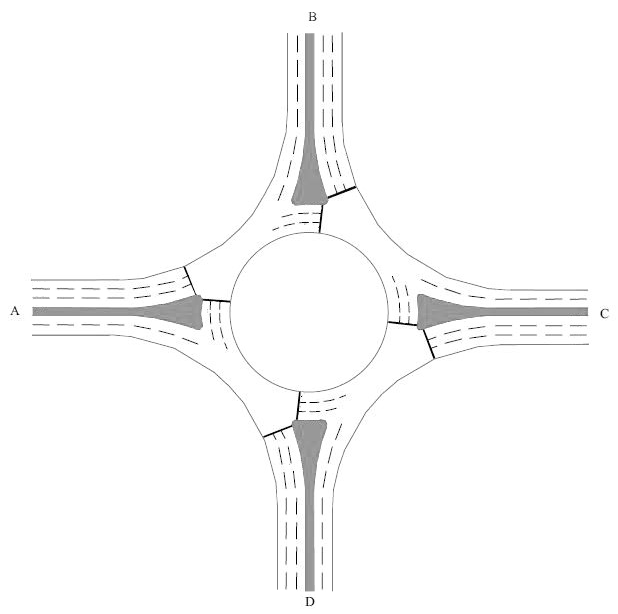
NOTE 2 For a normal roundabout, where the arms are well separated (as illustrated in Figure 3.18N2), the entry angle is determined as the angle between the projected path of an entering vehicle and the path of a circulating vehicle, using the below methodology:
- construct the curve EF as the locus of the midpoint between the nearside kerb and the median line (or the edge of any traffic island or central reserve);
- construct BC as the tangent to EF at the give way line;
- construct the curve AD as the locus of the midpoint of (the used section of) the circulatory carriageway (a proxy for the average direction of travel for traffic circulating past the arm);
- the entry angle, , is measured as the acute angle between BC and the tangent to AD.
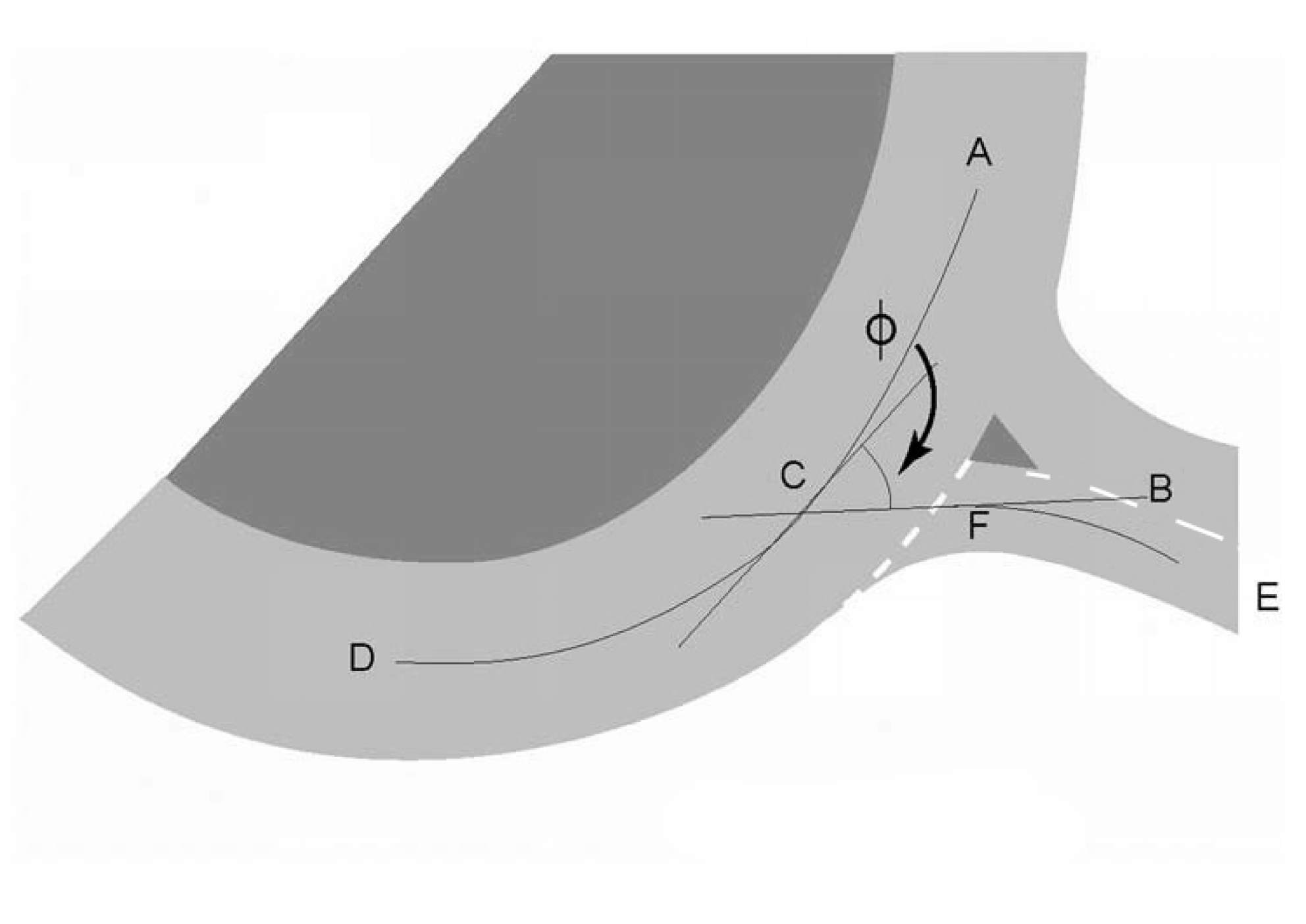
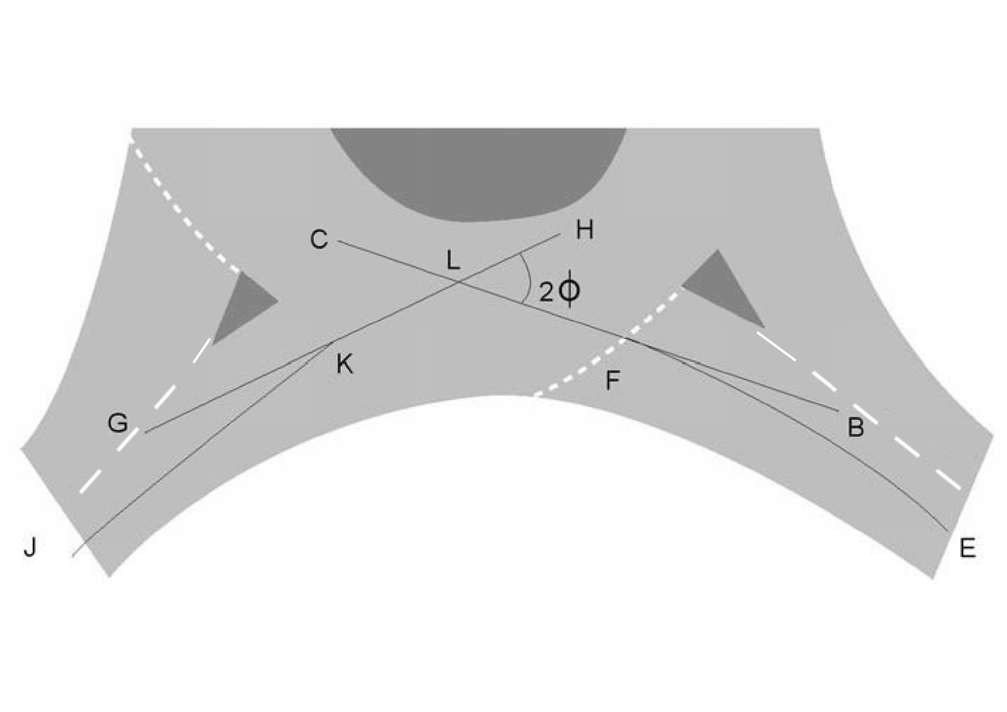
NOTE 3 For a compact roundabout or normal roundabout, where the arms are close together (as illustrated in Figure 3.18N3), the entry angle is determined as the angle between the projected path of an entering vehicle and the projected path of an exiting vehicle, using the methodology below:
- construct line BC as in Figure 3.18N3;
- construct the curve JK in the next exit as the locus of points midway between the nearside kerb and the median line (or the edge of any traffic island or central reserve);
- construct the line GH as the equivalent of line BC i.e. the tangent to the curve JK at the point where JK intersects the border of the inscribed circle;
- the lines BC and GH intersect at L;
- the entry angle, , is half of angle HLB. ( = [angle HLB]/2 , Note that if angle GLB exceeds 180 degrees, is defined as zero.)
NOTE 4 On a compact roundabout or normal roundabout, where the arms are close together, there can be insufficient separation between entry and adjacent exit to be able to define the path of the circulating vehicle clearly. In this case, circulating traffic which leaves at the following exit can be influenced by the angle at which that arm joins the roundabout.
3.18.1 The entry angle should be no less than 20 degrees and no greater than 60 degrees for normal and compact roundabouts.
NOTE 1 Small entry angles force drivers to look over their shoulders or use their mirrors to gauge a suitable gap to allow them to join the circulating traffic.
NOTE 2 Large entry angles tend to have lower capacity and can produce excessive entry deflection which can lead to sharp braking at entries, accompanied by shunt accidents, especially when approach speeds are high.
3.18.2 Except on compact roundabouts in urban areas, the kerb line of the traffic island (or central reserve in the case of a dual carriageway) should lie on an arc which, when projected forward, meets the central island tangentially (see Figure 3.18.2).
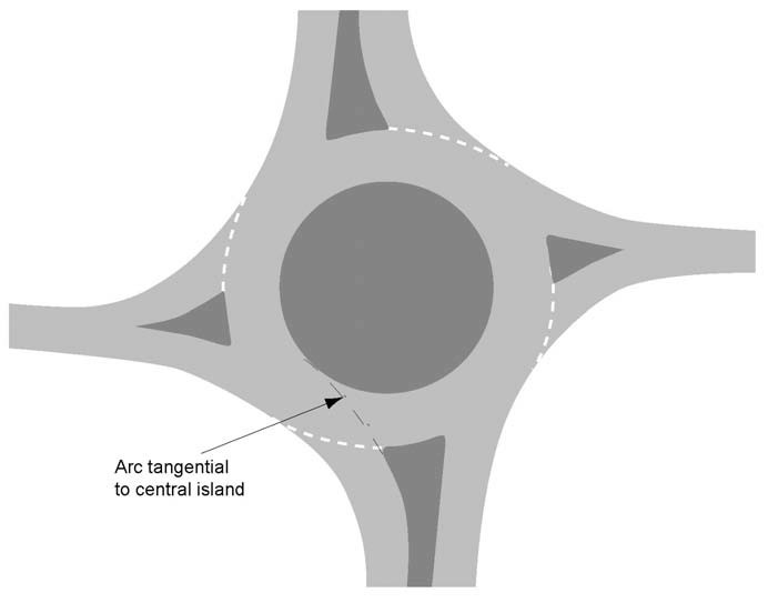
NOTE Aligning the kerb line with the central island as shown on Figure 3.18.2 reduces the likelihood of vehicle paths overlapping.
Entry kerb radius
3.19 The entry kerb radius shall be measured as the minimum radius of curvature of the nearside kerb line over the distance from 25 metres upstream of the give way line to 10 metres downstream of it (see Figure 3.19).
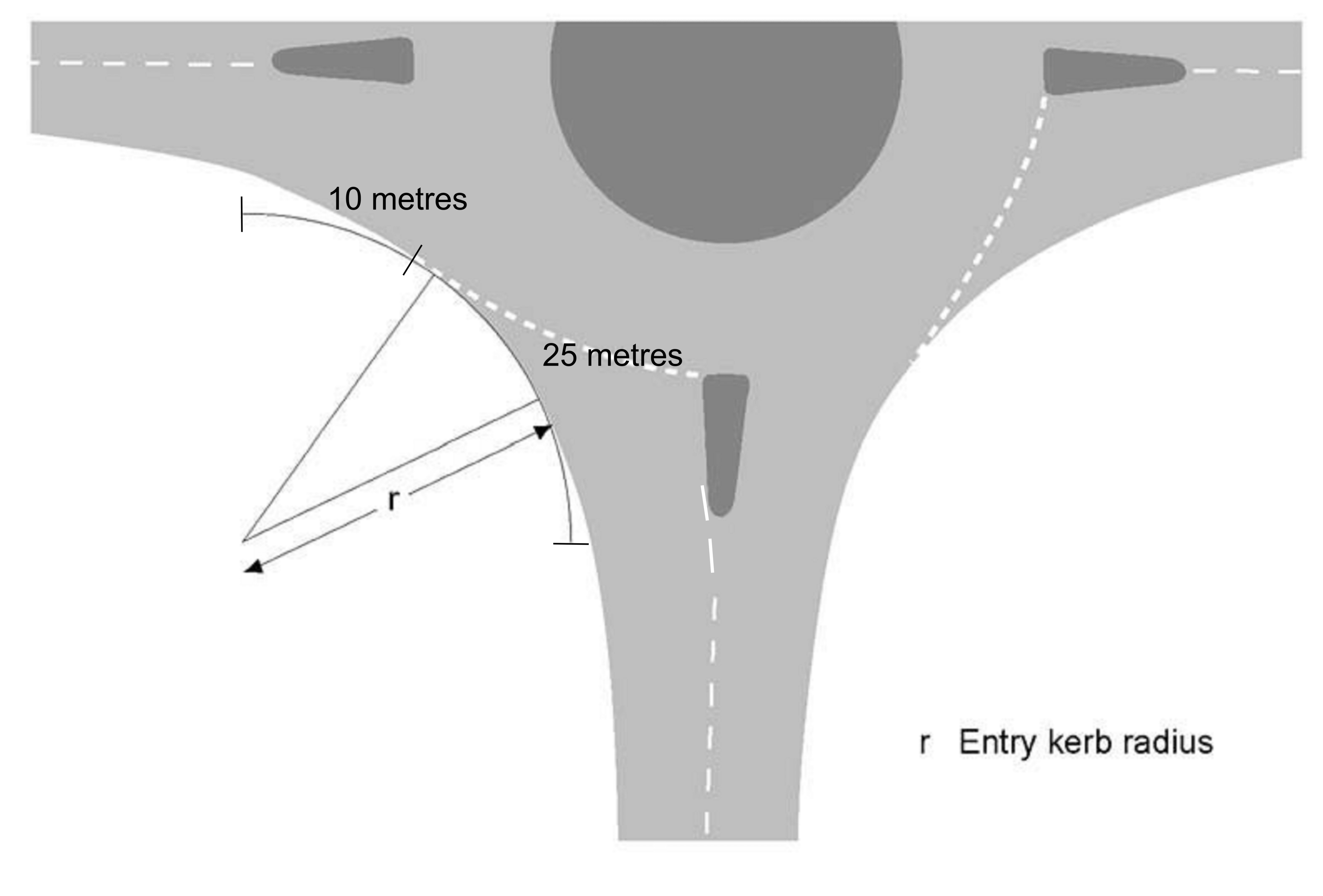
NOTE The entry kerb radius is the radius of the best fit circular curve measured over a length of 25 metres within a 35- metre zone.
3.19.1 The entry kerb radius should not be less than 10 metres.
3.19.2 The entry kerb radius should not be greater than 100 metres.
NOTE 1 An entry kerb radius of greater than 100 metres tends to result in inadequate entry deflection.
NOTE 2 Although entry capacity can be increased by increasing the entry kerb radius, once its value reaches 20 metres, further increases only result in very small capacity improvements. Reducing the entry kerb radius below 15 metre reduces capacity.
3.19.3 Except at compact roundabouts, if the approach is intended for regular use by HGVs, the entry kerb radii should not be less than 20 metres.
Entry path radius and deflection
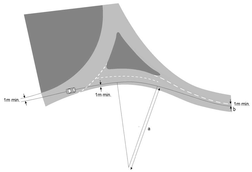
3.20 The entry path radius for an ahead movement at a 4-arm roundabout shall be determined as shown on Figure 3.20.

NOTE 1 The entry path radius (shown as 'a' on Figures 3.20, 3.22 and 3.23) is measured as the smallest best fit circular curve over a distance of 25 metres occurring along the approach entry path in the vicinity of the give way line, but not more than 50 metres in advance of it.
NOTE 2 The commencement point (shown as 'b' on Figures 3.20, 3.22 and 3.23) is 50 metres in advance of the give way line and at least 1 metre from the nearside kerb or centre line (or edge of central reserve).
NOTE 3 Further advice on constructing the entry path radius is provided in Appendix A.
3.21 The entry path radius (or its inverse, entry path curvature) shall be measured for all turning movements at a roundabout, except at a through-about approach arm for the through route.
NOTE The entry path radius is a measure of the deflection to the left imposed on vehicles entering a roundabout. It is the most important determinant of safety at roundabouts because it governs the speed of vehicles through the junction and whether drivers are likely to give way to circulating vehicles.
3.21.1 Where there is a turning movement at a through-about approach arm for the through route, entry deflection should be provided to turning vehicles, such that the entry angle is no less than 20 degrees and no greater than 60 degrees.
3.22 The entry path radius for the left-turn movement where the approach to the roundabout curves to the left shall be determined as shown on Figure 3.22.

3.23 The entry path radius for the left-turn movement where the approach to the roundabout curves to the right shall be determined as shown on Figure 3.23.
3.24 At compact roundabouts in urban areas, where the speed limit is 40 mph or less within 100 metres of the give way line on any approach, the entry path radius shall not exceed 70 metres.
NOTE On roads with a speed limit of 40 mph or less within 100 metres of the give way line on all approaches, compact roundabouts can have low values of entry and exit radii in conjunction with high values of entry deflection.
3.25 At compact roundabouts where the speed limit is 50 mph or greater within 100 metres of the give way line on any approach, the entry path radius shall not exceed 100 metres.
3.26 At normal roundabouts, the entry path radius shall not exceed 100 metres.
3.26.1 In order to ensure that the entry path radius provides suitable deflection, the arms may be staggered as shown in Figure 3.26.1.
NOTE 1 Staggering the arms as shown in Figure 3.26.1 can:
- reduce the size of the roundabout;
- minimise land acquisition;
- help to provide a clear exit route with sufficient width to avoid conflicts.
NOTE 2 In advance of the entry flare, approach curvature follows CD 109 [Ref 4.N] requirements on horizontal radii.
3.26.2 On normal and compact roundabouts, where sufficient entry deflection cannot be achieved by means of the central island alone, deflection should be generated by enlarging traffic islands or by providing a central overrun area for HGVs.
3.26.3 On existing normal and compact roundabouts, subsidiary deflection islands (SDI) may be used:
- where inadequate entry deflection is leading to operational and safety problems; and,
- where it is not possible to improve deflection by increasing the size of the central island and/or extending the traffic islands.
NOTE Requirements and advice on the provision of a subsidiary deflection are provided in Section 7, "Design of subsidiary deflection islands".
3.26.4 On normal and compact roundabouts, where an overrun area is provided, the entry path radius should be measured relative to the perimeter of this area rather than that of the central island.
Lane direction markings
3.27 Right pointing arrows on lane dedication signs or as markings on the road shall not be used on normal and compact roundabout approaches.
NOTE 1 Preventing the use of right pointing arrows on lane dedication signs or as road markings is to avoid confusing drivers, particularly those from overseas, over which way to proceed around the roundabout.
NOTE 2 Further guidance on the use of road markings is provided in Appendix D.
3.27.1 Where a right-hand lane is dedicated to a specific destination, it should be associated with an ahead arrow on the approach.
3.27.2 A right pointing arrow may be used on the circulatory carriageway.
3.27.3 Where any particular lane is dedicated to a specific destination the other lanes should also have arrow markings.
3.27.4 Where any particular lane is dedicated to a specific destination the road markings should be accompanied by direction signing indicating lane dedication.
3.27.5 Left turn arrows should be avoided on the circulatory carriageway.
NOTE Left turn arrows can sometimes lead to drivers mistakenly turning into roundabout entries.
3.27.6 Where lane direction markings have been, or are to be used on the approaches of a particular arm, then the direction markings within the entry lanes should be an extension of those markings in a logical and consistent manner, using the same designation system as those upstream (Figures 3.27.6a and 3.27.6b).


3.27.7 Where no approach markings have been provided, then the entry markings should be designed to give an even balance of any queuing traffic over the entry lanes whilst providing a smooth path onto the roundabout.
NOTE Arrow markings and route destinations can be particularly beneficial for larger, more complex roundabouts, especially those that have more than four entry/exit arms.
3.27.8 Approach lane markings should be positioned in advance of the give way line in a location where they are not obscured by queuing vehicles, and in a manner which balances the traffic between the approach lanes.
NOTE 1 Approach lane markings near to the give way line can result in drivers switching lanes too close to the junction.
NOTE 2 Further guidance is provided in TSM Chapter 5 [Ref 14.N].
3.27.9 Dedicated lane signs and associated road markings should be used on the approach to a signal-controlled roundabout where a single lane divides into separate lanes.
NOTE Dedicated lane signs are not appropriate for use where a lane is shared use, for instance where a lane is used for ahead and turning traffic.
Exits
Exit width
3.28 On normal and compact roundabouts, the exit width shall be measured as the distance between the nearside kerb and the edge of the traffic island (or central reserve of a dual carriageway) where it intersects with the outer edge of the circulatory carriageway, as shown on Figure 3.28.
NOTE As with entry width, exit width is measured normal to the nearside kerb. Values are typically similar to or slightly less than entry widths (exits have less flaring).
3.28.1 The exit width for normal roundabouts should accommodate one more traffic lane than is present on the link downstream.
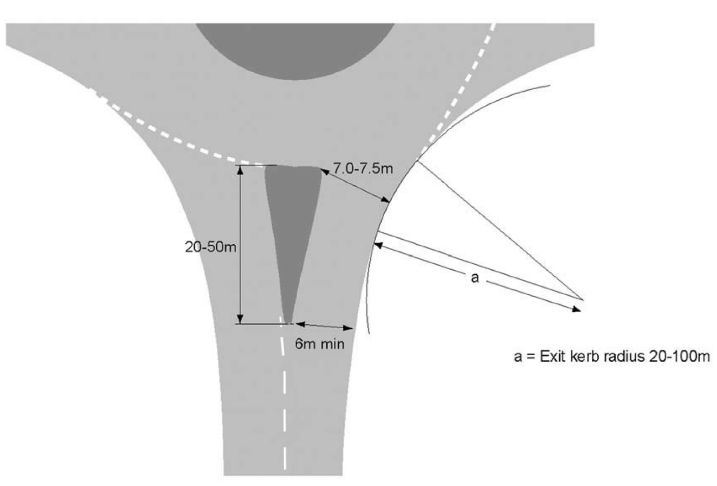
3.28.2 At a normal roundabout, if the downstream link is a single carriageway road, the exit width should be between 7 metres and 7.5 metres and the exit should taper down to a minimum of 6 metres.
NOTE The additional width allows traffic to pass a broken down vehicle.
3.28.3 Where the downstream link is a single carriageway road, the exit width should reduce at a taper of 1:15 to 1:20, starting at the end of the exit from the roundabout, ensuring 6 metres at end of traffic island, to avoid exiting vehicles encroaching onto the opposing lane at the end of the traffic island.
NOTE The exit width taper of 1:15 to 1:20 is for use on tapers on exit from the roundabout, not at locations where a differential acceleration lane (DAL) has been added.
3.28.4 At a normal roundabout, if the downstream link is an all-purpose two-lane dual carriageway, the exit width should be between 10 metres and 11 metres, with the exit tapering down to two lanes wide.
3.28.5 For non-signal-controlled roundabouts, vehicle swept paths should be assessed using the largest vehicle anticipated to use each exit lane.
3.28.6 Where traffic is required to merge after exiting, sufficient distance should be provided from the exit to allow the merging manoeuvre to take place in a safe and efficient manner.
3.28.7 Any exit line markings associated with the concentric-spiral, or spiral type of markings should be designed so as to provide a smooth exit from the circulatory carriageway.
NOTE 1 For smaller roundabouts, the use of lane direction arrows, route numbers and destinations at exits can confuse drivers and clutter the circulatory carriageway.
NOTE 2 For larger roundabouts, markings can be useful where a driver in a circulatory lane is presented with the choice of either exiting the roundabout, or continuing to circulate.
NOTE 3 Further advice on concentric-spiral and spiral markings is provided in Appendix D.
3.28.8 Where the peak exit volume approaches the capacity of the downstream link, tapers longer than 1:20 may be provided.
NOTE A taper longer than 1:20 can help merge the traffic where the density in each lane is high.
3.28.9 Where the exit is on an up gradient, the exit width may be maintained for a short distance before tapering in.
3.28.10 Where the exit road is on an up gradient combined with an alignment which bends to the left, the exit width may be maintained over a longer distance.
NOTE Maintaining the exit width can help drivers to overtake slower moving vehicles and Differential Acceleration Lanes (DALs) can provide further overtaking opportunities on exit arms with higher traffic flows.
3.28.11 At a compact roundabout, the exit width should be similar to the entry width.
Exit kerb radius
3.29 The exit kerb radius shall be measured as shown in Figure 3.28.
3.29.1 At normal roundabouts the exit kerb radius should exceed the largest entry radius.
3.29.2 At normal roundabouts, the exit kerb radius should be 40 metres.
3.29.3 Where an exit kerb radius of 40 metres cannot be achieved, the exit kerb radius should be no less than 20 metres and no greater than 100 metres.
NOTE The shortest distance possible between an entry arm and the next exit is governed by the minimum entry radius and the minimum exit radius for the type of roundabout in question.
3.29.4 A higher exit kerb radius may be used on normal roundabouts with larger ICDs on high speed roads to suit the overall junction geometry.
NOTE A compound curve starting with a 40 metre radius and developing to a larger radius, of up to 100 metres, can be used.
3.29.5 At compact roundabouts the exit kerb radius should be equal to the largest entry radius.
3.29.6 At a compact roundabout, the value of the exit kerb radius should be no less than 15 metres and no greater than 20 metres.
3.29.7 Larger values of exit radius, which lead to high exit speeds, should not be located where there are significant numbers of cyclists using the junction or where pedestrian crossing facilities are located immediately downstream.
3.29.8 Exits should be checked to ensure that vehicle paths are smooth and vehicles are not directed towards traffic islands.
NOTE Sharp turns into exits can increase the likelihood of load shedding by HGVs and decrease the traffic capacity of the junction.
3.29.9 On an exit, traffic islands should end at a tangent (or, at least, parallel) to the centre line and be long enough to prevent an exiting vehicle from crossing the centre line into oncoming traffic.
Differential acceleration lanes (DALs) and climbing lanes at roundabouts
3.30 DALs shall have a minimum length of 250 metres.
3.30.1 DALs may be provided on the exit from normal roundabouts to enable vehicles leaving the roundabout to overtake slower vehicles.
NOTE Requirements and advice for climbing lanes on the approach to and exit from roundabouts are provided in CD 109 [Ref 4.N].
3.31 DALs shall be designed in accordance with Figure 3.31.
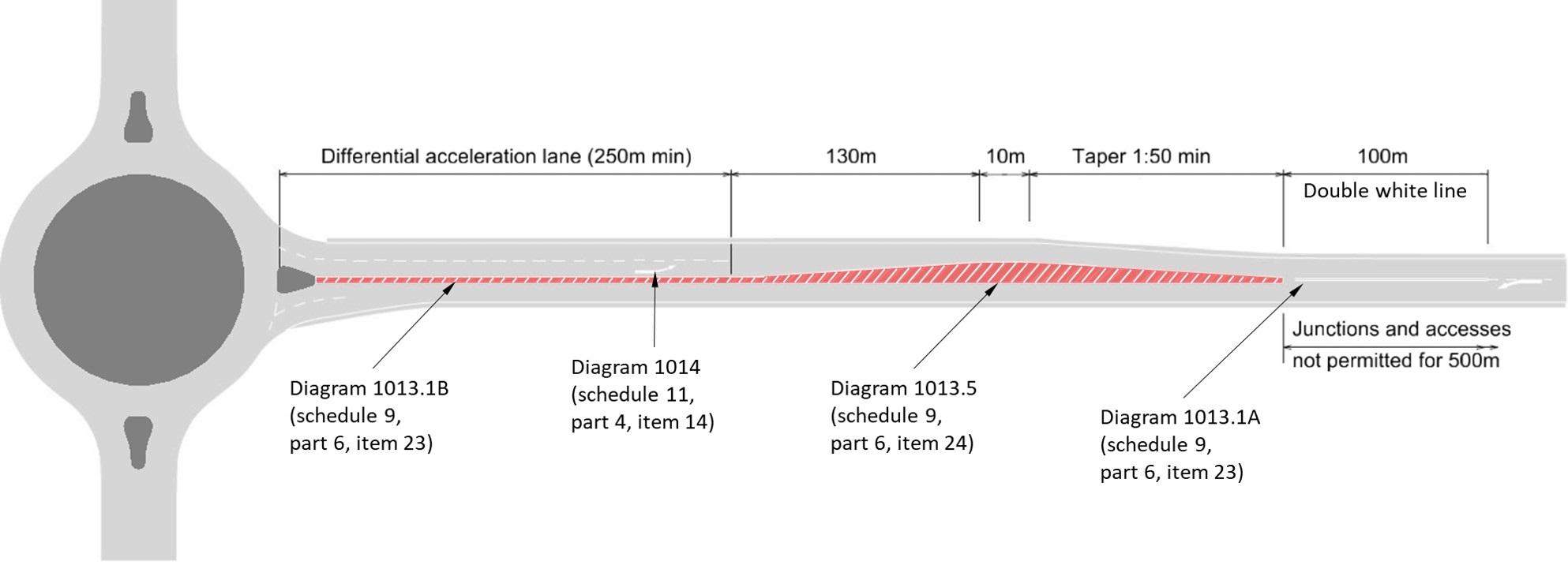
NOTE The transition in cross-section on the DAL is to be applied over the length of the taper. All dimensions on the cross-section are shown in metres.
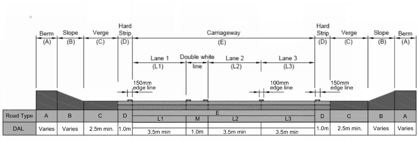
3.32 The DAL cross-section shall be in accordance with Figure 3.32.
3.33 The double white line road marking system separating the directions of flow on a DAL shall be to The Traffic Signs Regulations and General Directions UKSI 2016/362 (TSRGD) [Ref 9.N] diagram 1013.1B (schedule 9, part 6, item 23).
3.34 Road markings on a DAL in accordance with UKSI 2016/362 (TSRGD) [Ref 9.N]diagram 1013.1B (schedule 9, part 6, item 23) shall incorporate differential coloured surfacing.
NOTE Requirements and advice for coloured surfacing are contained in CD 236 [Ref 7.N].
3.35 The white lines on a DAL in accordance with UKSI 2016/362 (TSRGD) [Ref 9.N] diagram 1013.1B (schedule 9, part 6, item 23) shall be 150 mm wide between the running lanes and the hardstrips of the DAL.
3.36 At the end of the DAL, the road markings in accordance with UKSI 2016/362 (TSRGD) [Ref 9.N] diagram 1013.1B (schedule 9, part 6, item 23) shall change to the wider road marking to UKSI 2016/362 (TSRGD) [Ref 9.N] diagram 1013.5 (schedule 9, part 6, item 24) as shown in Figure 3.31 and Figure 3.36.
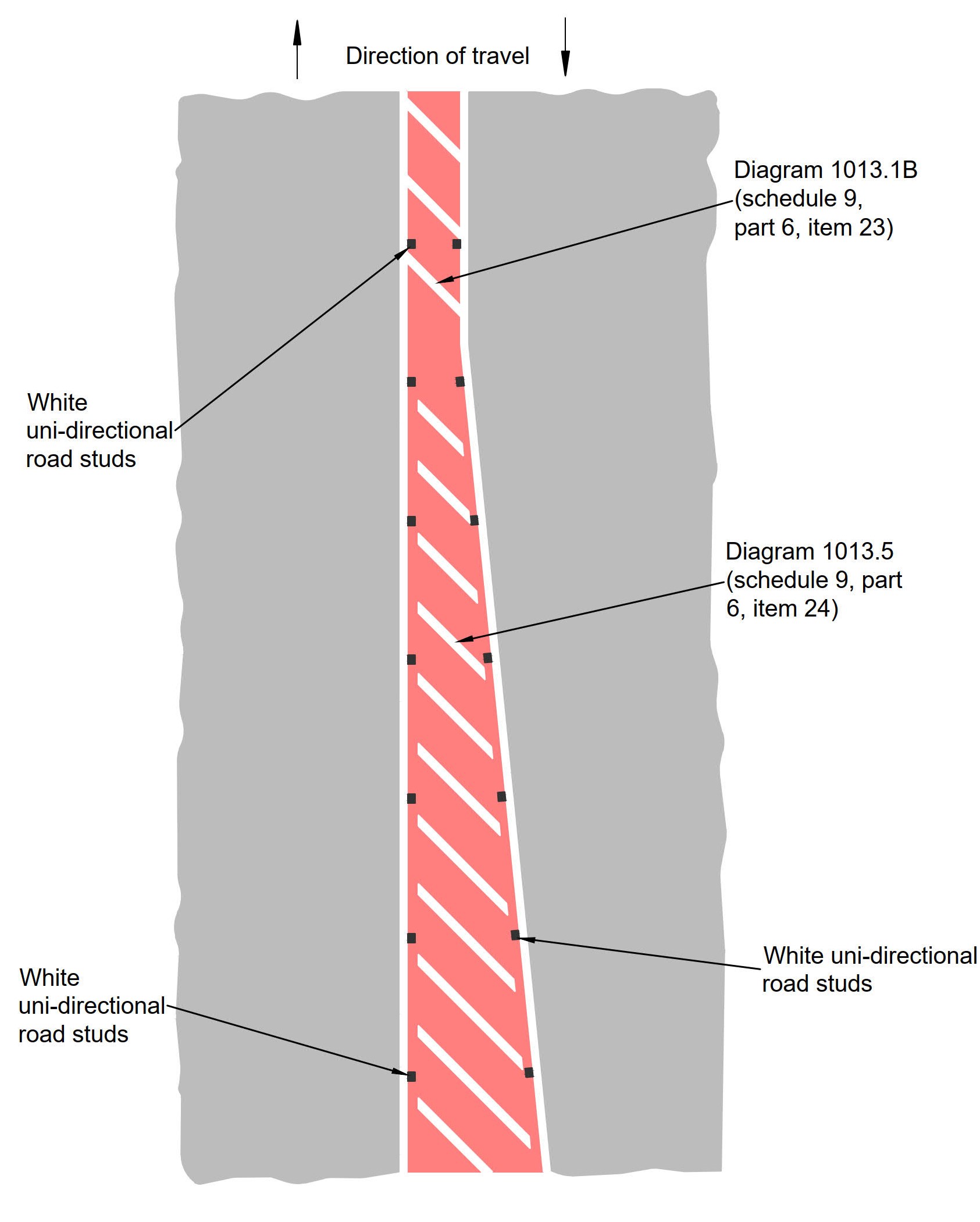
3.37 Road markings on a DAL in accordance with UKSI 2016/362 (TSRGD) [Ref 9.N] diagram 1013.1B (schedule 9, part 6, item 23) and 1013.5 (schedule 9, part 6, item 24) shall be fitted with studs in pairs, within the width of each of the two lines, as shown in Figure 3.36.
NOTE TSM Chapter 5 [Ref 14.N]) provides further guidance on the placement of studs.
3.38 The studs used in the DAL road markings shall be uni-directional so that only reflectors on the line of studs, adjacent to the road users direction of travel, face the road user.
3.39 Junctions and accesses shall not be located on DALs, their associated tapers or within 500 metres of the end of the taper.
Crossfall and gradients
3.40 A crossfall profile shall be provided on approaches, entries, exits and circulatory carriageways of a roundabout for the purpose of draining surface water.
3.40.1 On circulatory carriageways, the crossfall should not be steeper than 2.5% (1 in 40).
NOTE 1 Crossfall is required to drain surface water on circulatory carriageways. The typical value for crossfall on circulatory carriageways is 2% (1 in 50).
NOTE 2 At compact roundabouts and small normal roundabouts where the speed limit within 100 metres from the give way line does not exceed 40 mph on any approach, the crossfall can slope outwards to ease drainage and help keep speeds down. It also makes the central island more conspicuous.
3.40.2 At compact roundabouts and small normal roundabouts, constant crossfall should be applied in one direction across the full width of the circulatory carriageway.
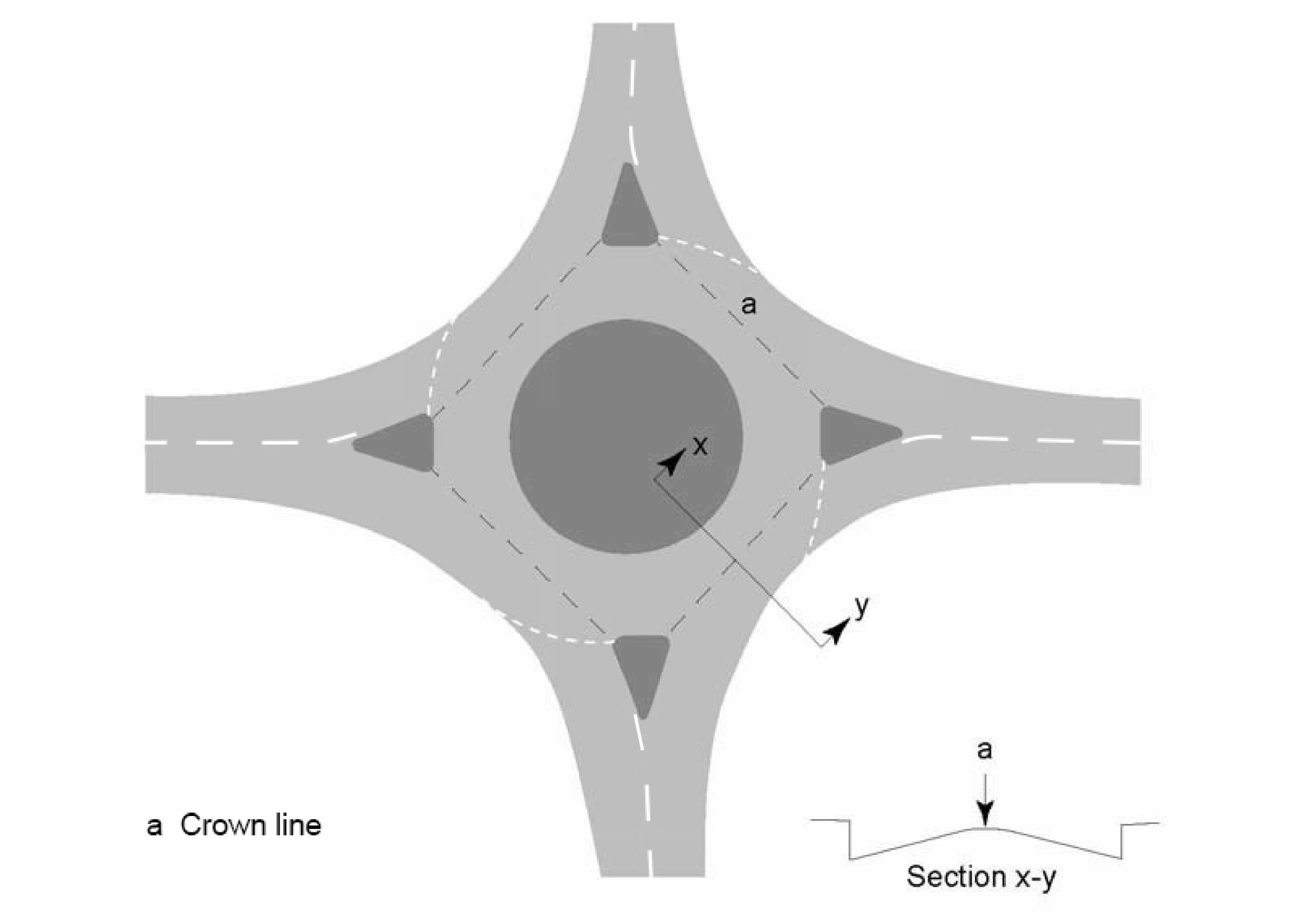
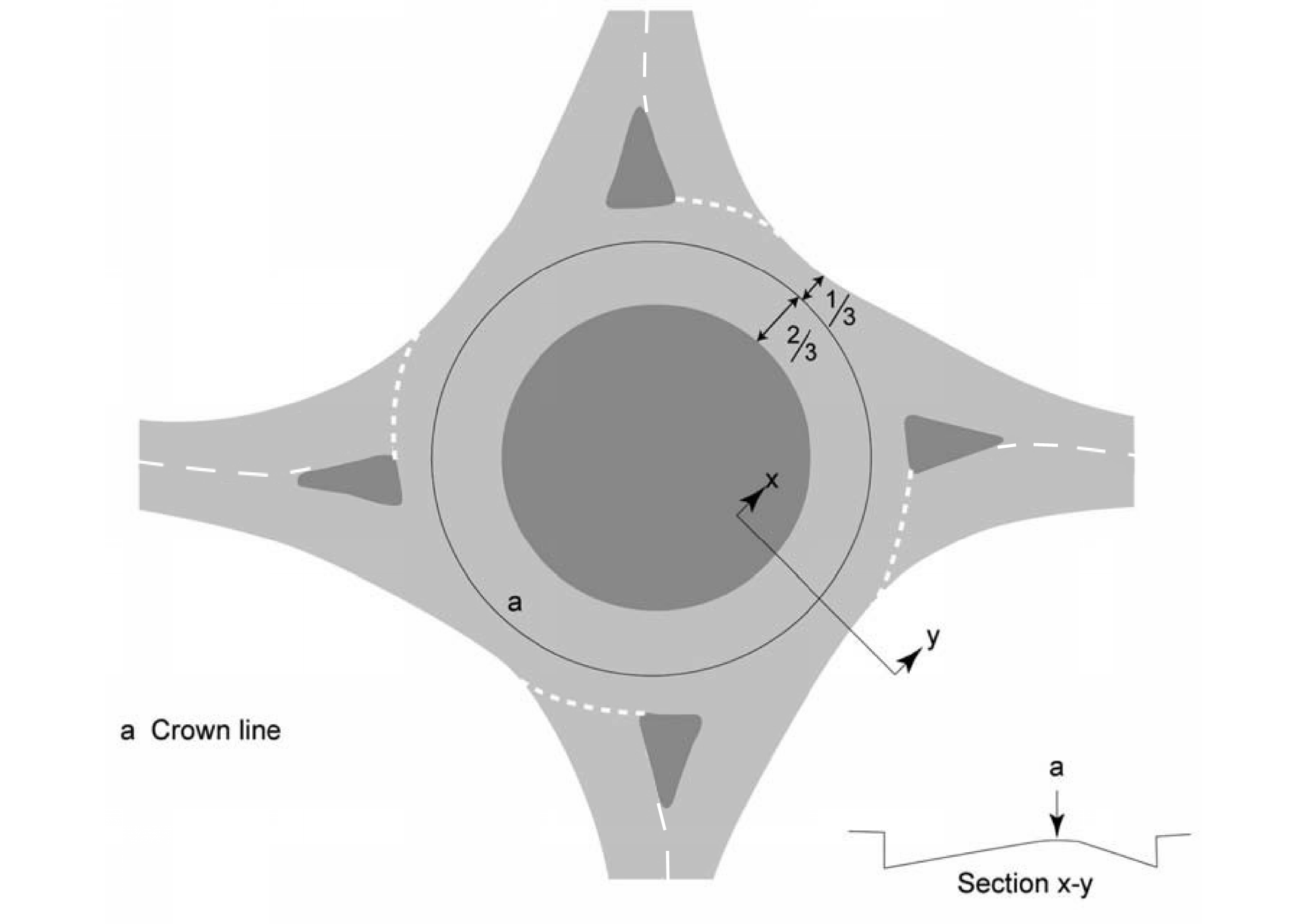
3.40.3 At normal roundabouts on high speed roads, crossfall may be provided to assist vehicles traversing the roundabout by forming a crown line.
NOTE 1 The crown line can either join the ends of the traffic islands as shown in Figure 3.40.3N1a, or divide the circulatory carriageway in the proportion 2:1 internal to external (Figure 3.40.3N1b).
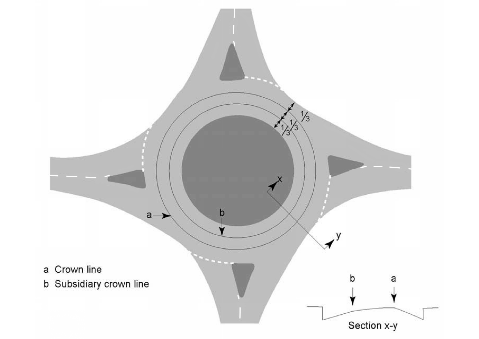
NOTE 2 In some cases, a subsidiary crown line can assist in achieving appropriate values of crossfall without giving excessive changes at the main crown line (Figure 3.40.3N2).
NOTE 3 The crown line can also be designed utilising the methodology indicated in the Stockdale Method [Ref 16.I].
3.40.4 Over a given section of circulatory carriageway, a maximum arithmetic difference in crossfall of 5% should be used.
NOTE 1 Lower values of crossfall change less than 5% are desirable, particularly for roundabouts with a small ICD.
NOTE 2 Conflicting crossfalls at the crown lines have a direct effect on driver comfort and can also be a contributory factor in load shedding and HGV roll-over accidents.
NOTE 3 Load shedding is often caused by a desired vehicle path crossing a crown line too square which results in the need for the vehicle to manoeuvre through an abrupt change in crossfall.
3.40.5 Sharp changes in crossfall should be avoided.
3.40.6 Changes in crossfall on the circulatory carriageway should be designed to provide a smooth crown.
3.40.7 To avoid ponding, longitudinal edge profiles should be graded at not less than 0.67% (1 in 150), with 0.5% (1 in 200) the minimum in exceptional circumstances.
NOTE The design gradients do not in themselves ensure satisfactory drainage, and, therefore, the correct siting and spacing of drainage system elements is critical.
3.40.8 On large roundabouts, the applied superelevation may provide the crossfall.
3.40.9 Longitudinal gradients on the approach to a roundabout should not exceed 2% over a distance of at least 20 metres, measured from the give way or stop line.
NOTE 1 Crossfall and longitudinal gradient combine to provide the necessary slope to drain surface water from the carriageway.
NOTE 2 Providing a relatively flat section reduces the risk of vehicles stalling, rolling backwards or rolling out into the roundabout circulatory carriageway.
NOTE 3 As part of the road alignment design for the roundabout approaches, a longitudinal gradient can be “smoothed out” on the immediate approach to the give way or stop line by use of an appropriate vertical crest or sag curve in accordance with CD 109 [Ref 4.N].
3.41 On the approaches and exits, the applied superelevation shall not exceed 5% (1 in 20).
3.41.1 On the approaches and exits, the applied superelevation should be equal to or greater than that necessary for surface drainage.
3.41.2 At 20 metres on the approach to the give way line, superelevation should be reduced to 2%.
NOTE The superelevation can be reduced to 2% as the provision of adequate advance signing and entry deflection encourages reduction of speed on approach.
3.41.3 At exits, crossfall adjacent to the roundabout should not exceed 2%.
NOTE At exits, superelevation can be provided to allow vehicles to accelerate safely away from the roundabout.
3.41.4 Where a roundabout exit leads into a right-hand curve, superelevation should be introduced gradually.
Visibility
3.42 Visibility shall be measured in accordance with the envelope of visibility for measurement of stopping sight distance (SSD) in CD 109 [Ref 4.N], with visibility obtainable from a driver’s eye height of between 1.05 metres and 2 metres to an object height of between 0.26 metres and 2 metres, except for:
- visibility to the right at entry; and
- across the central island.
NOTE 1 Requirements and advice for visibility to the right and circulatory visibility are covered in sub-sections "Visibility to the right" and "Circulatory visibility".
NOTE 2 The visibility requirements in this section include no obstructions due to signs, street furniture or planting. Sign mounting heights on the central reserve of no less than 2 metres above the carriageway surface are likely to meet the visibility requirements of this section.
NOTE 3 Isolated objects less than 550mm wide such as lighting columns, sign supports or bridge columns are acceptable.
Forward visibility on approach (SSD)
3.43 On a 7.3 metres wide dual carriageway, SSD shall be measured to the position of an object at the give way line (5.5 metres from the traffic island) as shown on Figure 3.43.
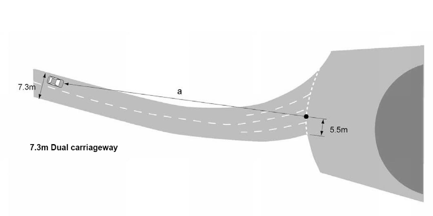
3.44 On a 10 metre wide single carriageway, SSD shall be measured to the position of an object at the give way line (5.5 metres from the edge of the traffic island) as shown on Figure 3.44.
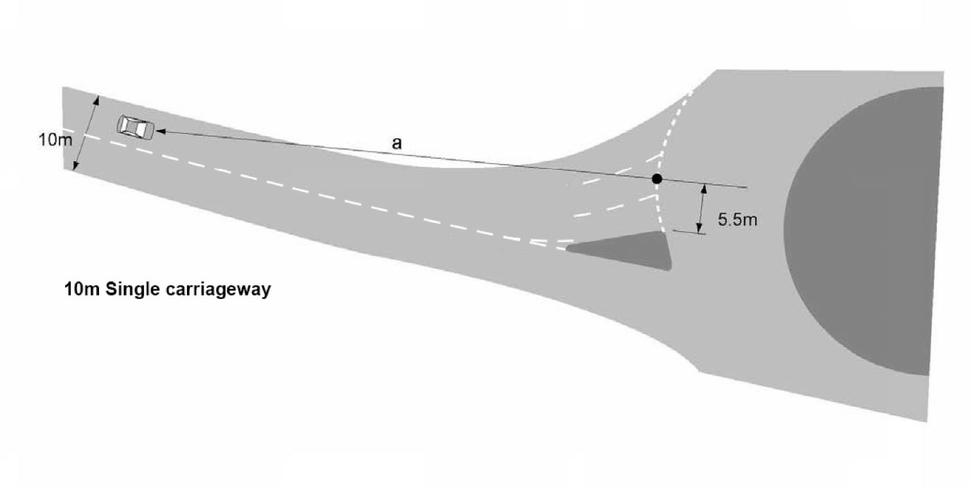
3.45 On a 7.3 metre wide single carriageway, SSD shall be measured to the position of an object at the give way line (3.65 metres from the edge of the traffic island) as shown on Figure 3.45.
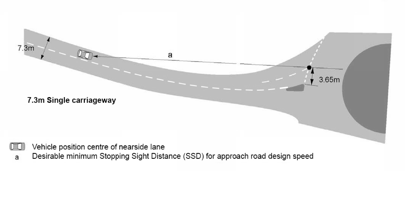
3.46 Visibility on the approach, 'a', to the roundabout shall conform to CD 109 [Ref 4.N].
NOTE 1 On high speed dual carriageway approaches, the provision of transverse yellow bar markings can reduce rear shunt and overshoot accidents by helping to alert the driver to the presence of the roundabout. On high speed single carriageway roads on which drivers fail to adjust their speed in time to negotiate the roundabout safely or to stop, the provision of ‘Reduce Speed Now’ signs can have a similar effect. Transverse yellow bar markings are only to be used in certain circumstances, refer to TSM Chapter 5 [Ref 14.N] and TRL LR 1010 [Ref 21.I] for further guidance.
NOTE 2 Visibility on the approach, 'a' shown on Figures 3.43, 3.44 and 3.45, is the desirable minimum SSD for the design speed of the road.
NOTE 3 The visibility on the approach is measured from a vehicle position in the centre of the nearside lane, measured from the centre of the lane as shown on Figures 3.43, 3.44 and 3.45.
3.47 Where chevron signs are located on the central island, they shall be visible to approaching drivers in all lanes from a distance equal to the desirable minimum SSD measured back along the approach lanes from the give way line.
NOTE The desirable minimum SSD is measured back from the give way line as this is the point at or before which road users need to be able to reduce speed.
3.48 Where chevron signs are used, the signs shall not be stacked.
3.48.1 Where the chevron signs are inconspicuous, yellow backing boards or larger signs should be used.
3.48.2 Where the approach to the roundabout is over a crest, a higher sign mounting height may be used.
NOTE Chevron signs sometimes can impinge on circulatory visibility but the effects can be minimised by positioning the signs 2 metres back from the central island kerb line (further guidance regarding the positioning of signs is provided in TSM Chapter 4 [Ref 13.N]).
Forward visibility at entry for non-signal-controlled and part-time signal-controlled roundabouts
3.49 Drivers of all vehicles approaching the roundabout shall be able to see objects of height between 0.26 metres and 2 metres on the full width of the circulatory carriageway, from the centre of the nearside lane at a distance of 15 metres back from the give way line, for the visibility distance as shown in Table 3.49.
| ICD (metres) | Visibility distance (metres) ('a' in Figures) |
|---|---|
| < 40 | Whole junction |
| 40 - 60 | 40 |
| > 60 - 100 | 50 |
| > 100 | 70 |
NOTE The visibility distance given in Table 3.49 is measured along the centre of the circulatory carriageway as shown in Figure 3.49N.
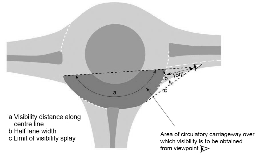
Visibility to the right for non-signal-controlled and part-time signal-controlled roundabouts
3.50 For visibility to the right, the envelope of visibility shall be obtainable from a driver’s eye height of between 1.05 metres and 2 metres to an object height of between 1.05 metres and 2 metres.
3.51 Drivers of all vehicles approaching the roundabout shall be able to see the full width of the circulatory carriageway to their right, from the centre of the offside lane at the give way line, for the visibility distance provided in Table 3.49 and as shown in Figure 3.51.
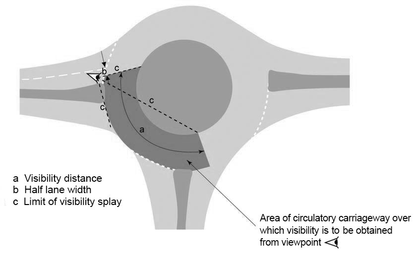
NOTE 1 The requirement for visibility to the right includes roundabouts with bridge parapets on either side of the circulatory carriageway.
NOTE 2 Where entry problems are caused by poor visibility to the right, visibility can be improved by extending the traffic island to narrow the circulatory carriageway and moving the give way line forward.
3.51.1 To reduce excessive approach speeds on dual carriageway approaches, visibility to the right may be limited by screening the vehicle until it is within 15 metres of the give way line.
NOTE Excessive visibility to the right can result in high entry speeds, potentially leading to overshoot accidents and to accidents for single vehicles and PTWs. Further accident mitigation can be provided by signing and marking, and by ensuring that the layout guides drivers around the central island.
3.51.2 Screening provided to reduce the visibility to the right should be at least 2 metres high in order to block the view of all road users.
NOTE Screening can be used on flared approaches on high speed single carriageway roads where there is a long traffic island.
3.52 Visibility to the right shall conform to Table 3.49 and be measured from the centre of the offside lane at a distance of 15 metres back from the give way line, as shown in Figure 3.52.
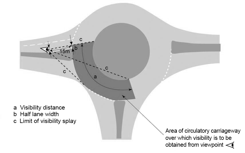
Circulatory visibility for non-signal-controlled, part-time signal-controlled and full time signal-controlled roundabouts
3.53 For circulatory visibility on non-signal-controlled and part-time signal-controlled roundabouts, the envelope of visibility shall be obtainable from a driver’s eye height of between 1.05 metres and 2 metres to an object height of between 1.05 metres and 2 metres.
3.54 This visibility shall be checked at a distance of 2 metres in from the central island, as shown in Figure 3.54.
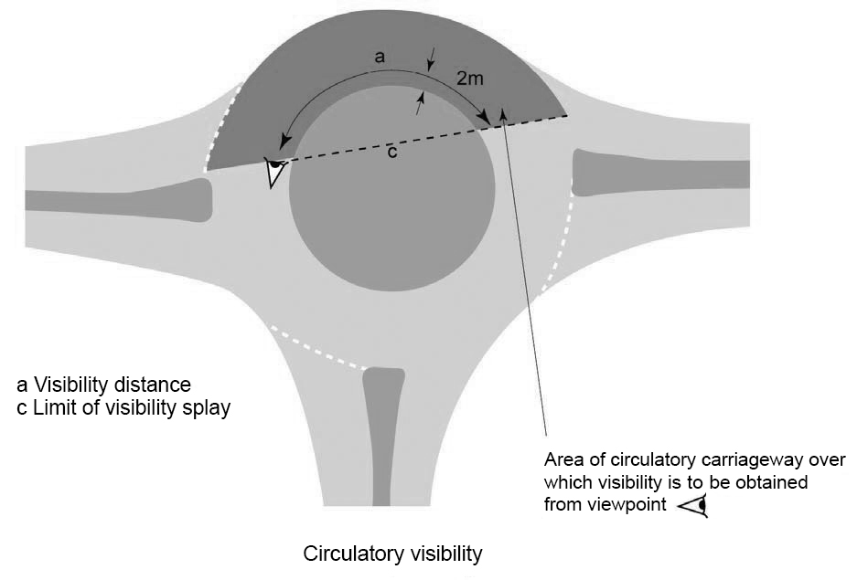
3.55 Drivers on the circulatory carriageway of non-signal-controlled and part-time signal-controlled roundabouts shall be able to see the full width of the circulatory carriageway ahead of them for the visibility distance given in Table 3.49.
NOTE It is often useful to improve the conspicuousness of central islands by landscaping, as long as circulatory visibility is not obstructed.
3.55.1 At least the outer 2 metres of the central island should be hard standing or planted with grass or similar low-level vegetation to prevent visibility issues occurring.
NOTE 1 Grass or similar low-level vegetation can potentially cause visibility issues if not regularly maintained and road worker risk needs to be considered when using this type of landscaping.
NOTE 2 Further requirements and advice for the landscape design of the central island are provided in LD 117 [Ref 8.I].
3.55.2 On a full-time signal-controlled roundabout, the circulatory visibility requirements for a non-signal-controlled roundabout should be applied.
NOTE Applying the same circulatory visibility for a full-time signal-controlled roundabout to that of a non-signal-controlled roundabout can help the signal-controlled roundabout to operate safely when the signals are not in use.
Exit visibility
3.56 On the circulatory carriageway, the exit visibility shall conform to Table 3.49.
NOTE CD 109 [Ref 4.N]provides requirements and advice regarding the SSD once a vehicle has crossed the inscribed circle at the exit from the roundabout.
Pedestrian crossing visibility
3.57 Drivers approaching a roundabout with a zebra crossing across the entry, shall be able to see the full width of the crossing from a distance at least equal to the desirable minimum SSD for the design speed of the roundabout approach.
3.58 Drivers approaching a roundabout with a signal-controlled crossing shall be able to see at least one signal head for desirable minimum SSD for the design speed of the roundabout approach.
3.59 At the give way line, drivers shall be able to see the full width of a pedestrian crossing (whether signal-controlled, zebra or informal) across the next exit if it is within 20 metres of the give way line on that arm, as shown on Figure 3.59.
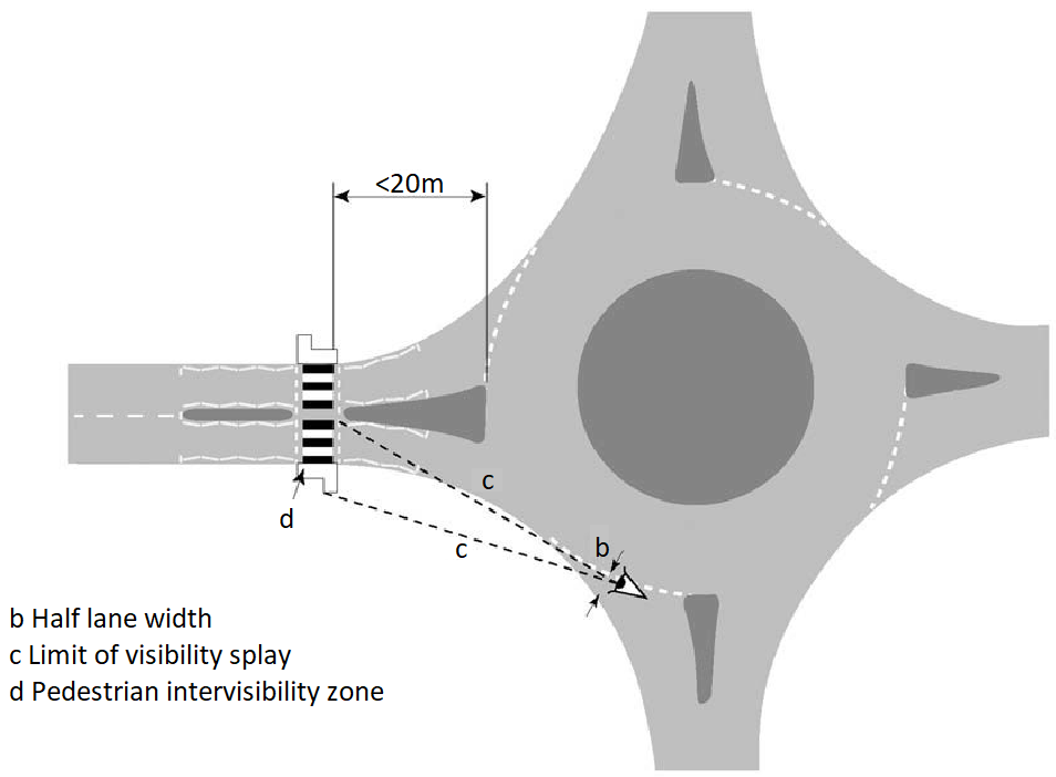
3.59.1 Crossings should not be sited between 20 metres and 60 metres from the give way line.
NOTE Requirements and advice for visibility to crossings for a signalised roundabout are given in CD 123 [Ref 3.N].
Hard strips, shoulders, kerbs and verge areas
3.60 Hard strips and hard shoulders on each approach shall terminate where entry widening begins.
NOTE The simplest procedure for terminating hard strips is to start the kerbs on the approach at the back of the hard strip and then terminate the hard strip edge line in a short smooth curve or taper (see Figures 3.60Na and 3.60Nb).
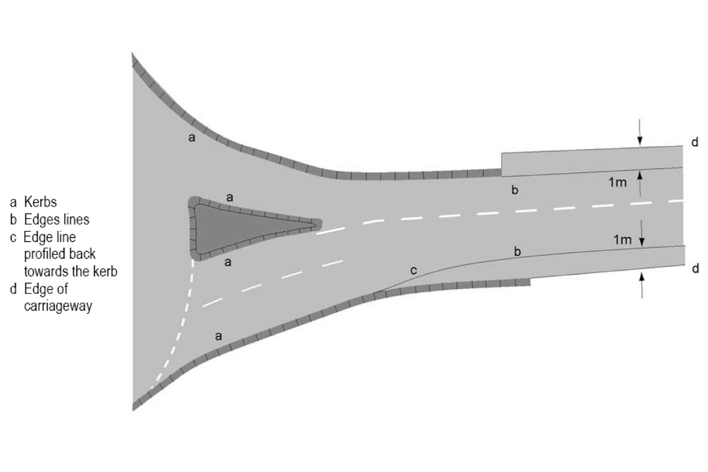
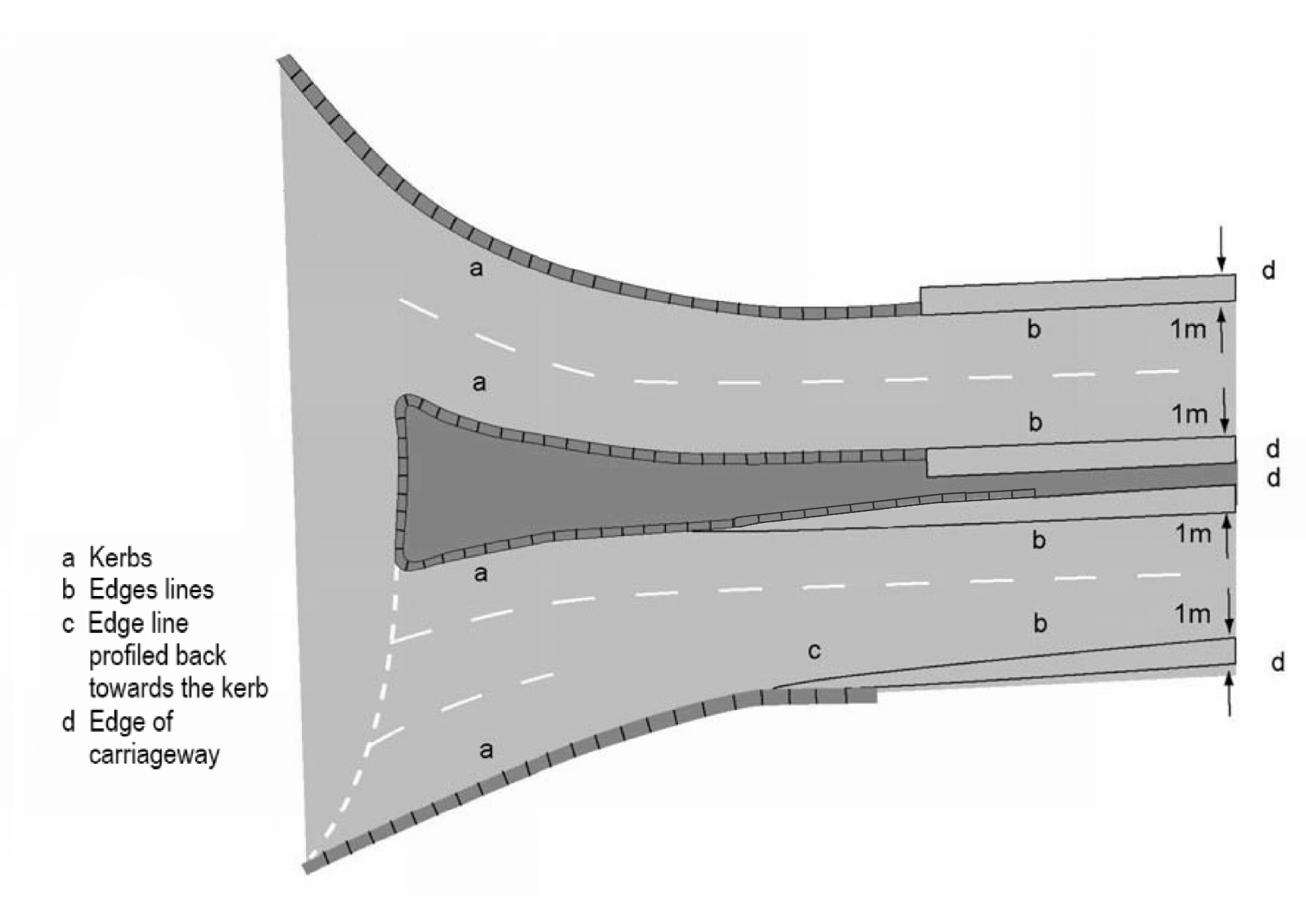
3.60.1 Roundabout entries and exits should be kerbed.
3.60.2 On entry, on both the nearside and offside, the initial kerb should be a dropped kerb and located before the hard strip begins to taper down.
3.60.3 On exits, the edge line should continue along the projected line of the kerbing once this is terminated (refer to Figures 3.60Na and 3.60Nb).
NOTE On the exit, the kerbing can terminate where the hard strip starts.
3.60.4 The verge width should be at least 2.5 metres and be consistent around the roundabout.
NOTE Further advice on verge width is given in CD 127 [Ref 1.N].
3.60.5 The verge width should be determined by assessing:
- visibility requirements;
- needs of WCHR users (refer to CD 143 [Ref 2.N];
- space required to accommodate buried services, road signs and other street furniture;
- maintenance access; and,
- any likely future traffic increases that could require an increase in carriageway width.
3.60.6 At dual carriageway and grade separated junctions, an area of hard standing to allow large vehicles to exit via the on-slip, should be checked using swept paths, whilst ensuring that the layout is safe and does not confuse road users during normal day-to-day operations.
3.60.7 At dual carriageway and grade separated junctions, an area of hard standing may be provided on either side of the exit arm, or on the central island, to allow for large vehicles exiting a motorway or dual carriageway road via the on-slip during major incidents and under police direction.
NOTE A hard standing enables large vehicles to enter and proceed around the roundabout in the normal direction.
4. Additional requirements and advice for design of signal-controlled roundabouts
General
4.1 Where the 85th percentile speed on the approach roads are greater than or equal to 104 kph (65 mph), a signal-controlled roundabout shall not be provided.
NOTE 1 Guidance on the provision of traffic signals at roundabouts is contained in LTN 1/09 [Ref 10.I] which discusses the specific traffic problems associated with roundabouts which can be resolved by the application of traffic signals, with or without the need for geometric changes.
NOTE 2 Roundabouts are not always suitable in urban areas as they are not always compatible with urban traffic control (UTC) systems. UTC systems move vehicles through controlled platoons, adjusting signal times to suit required progress, and roundabouts can disrupt platoon movements.
NOTE 3 Cycle provision requirements and advice for signal-controlled roundabouts are provided within CD 195 [Ref 3.I].
NOTE 4 The geometric design of a through-about follows the same geometric requirements and advice as normal roundabouts in this document for the roundabout specific elements, and follows the same geometric requirements and advice as signal-controlled junctions in CD 123 [Ref 3.N] where signal-controlled elements are considered.
NOTE 5 85th percentile speed measurement requirements and advice are provided within CA 185 [Ref 19.I].
Direct and indirect signal-control
4.2 Signal-controlled roundabouts shall be designed incorporating direct and/or indirect signal configuration.
4.2.1 When direct signal-control is used at a roundabout, as illustrated in Figure 4.2.1 for a large signalised roundabout, the signal control may be partial where traffic flows on the minor roads (Arms B and C in the figure) are light and continue to operate in a self-regulating manner under normal priority control.
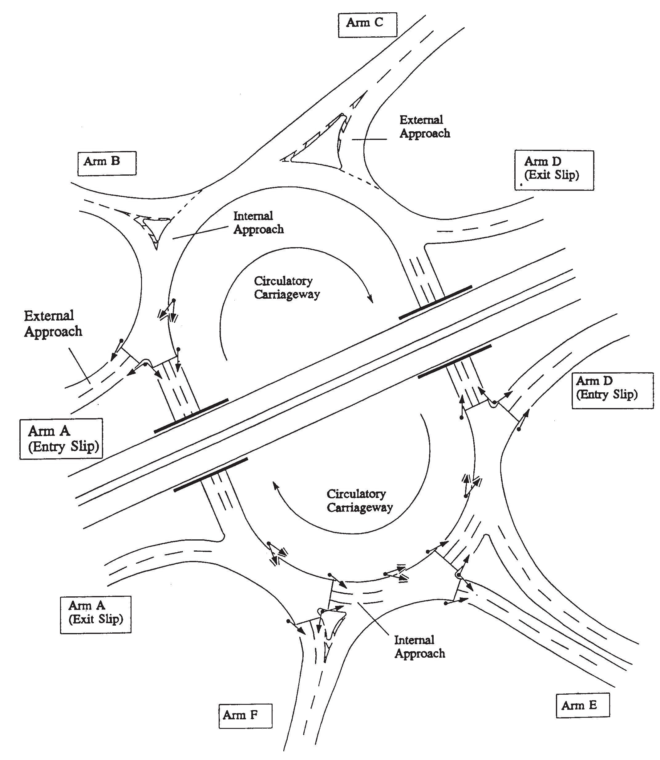
4.2.2 Where direct signal-control is applied to a roundabout, the effect of the internal queues on the roundabout should be assessed as part of the performance analysis of the roundabout during design.
NOTE 1 Under direct signal-control (as illustrated on Figure 4.2.1), the internal queuing capacity on the circulatory carriageway to the right of Arm E is limited by the width of the central reserve on the dual carriageway approach. Similarly, to the right of Arm F the internal queuing capacity is severely limited by the size of the deflection island.
NOTE 2 Internal approach lanes less than 15 metres in length can result in the blockage of the exit arm, particularly where HGVs are present.
4.2.3 Where a roundabout uses direct signal-control, the capacity on the internal approaches to Arms E and F (as illustrated on Figure 4.2.1) may be improved by geometric modifications to these external approaches by significantly reducing the entry radii.
NOTE Where a roundabout uses direct signal-control, the scope for geometric modifications is reduced due to the requirements for the design to be in accordance with Section 3.
4.2.4 Indirect signal-control may be used where an entry arm with a very heavy traffic flow is preceded by (that is, is to the left of) an entry arm with a very light traffic flow.
NOTE A heavy flow on a single roundabout arm can often proceed virtually uninterrupted, possibly with high circulatory speeds. This causes an unbalanced traffic flow which adversely affects the capacity of the roundabout and can lead to excessive queue lengths (and substantial delays) to other external approaches which in turn can result in congestion at preceding junctions or on slip roads.
4.2.5 The installation of indirect signal-control (as illustrated in Figure 4.2.5) may be introduced to control entry flows on one or more approaches and can provide a gap in the circulatory traffic, to favour those entry arms that were previously subjected to excessive delays and queues.
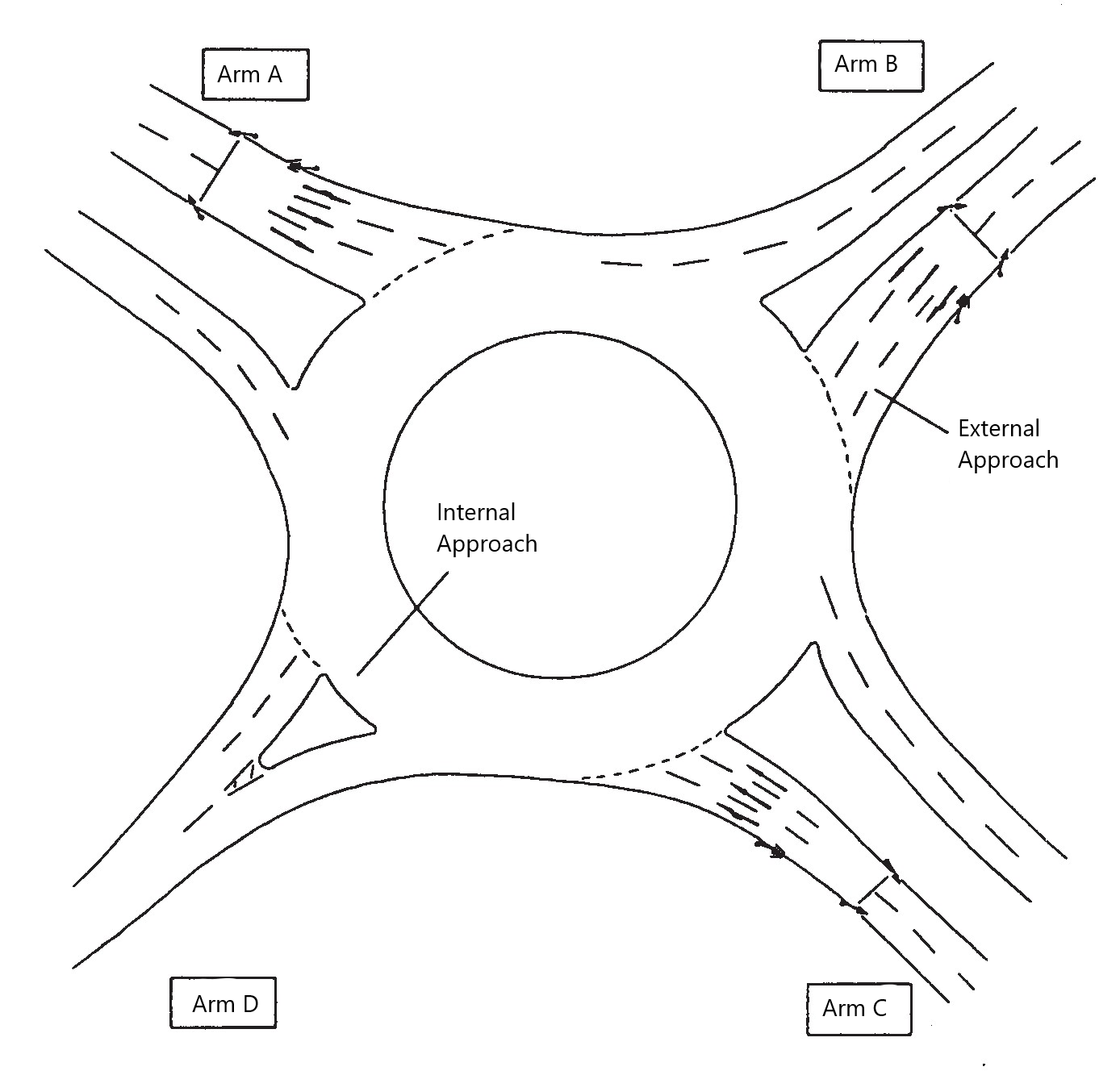
NOTE Indirect signal-control can balance the capacity of the entry arms, however increases in vehicle gap distances can be detrimental to cyclists and pedestrians crossing the arms.
Additional approach lane capacity on signal-controlled roundabouts
4.3 When an assessment demonstrates that additional approach lane capacity is needed on a signal-controlled roundabout, the additional lane(s) shall be provided adjacent to either the offside or nearside carriageway edge.
4.3.1 On a signalised roundabout, the provision of an additional offside external approach lane, may be used where:
-
- sufficient space is available on the offside, within the central median;
- a nearside approach lane could result in inadequate internal queuing capacity on the internal approach to the left;
- it does not significantly reduce the queuing capacity on the internal approach to the right.
NOTE Figure 4.3.1N illustrates the provision of an additional offside approach lane.
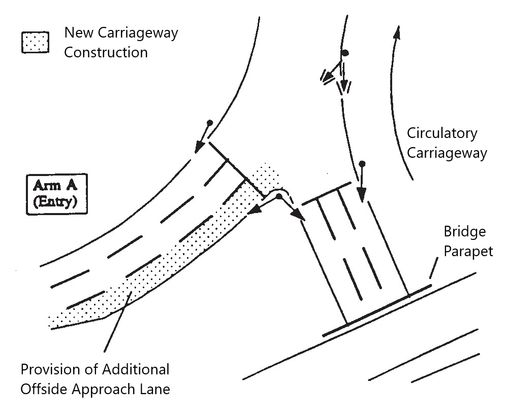
4.3.2 On signal-controlled roundabout, the provision of an additional nearside external approach lane may be used where:
-
- sufficient space is available on the nearside;
- an offside external approach lane could result in inadequate queuing capacity on the internal approach to the right;
- it does not significantly reduce the queuing capacity on the internal approach to the left.
NOTE 1 Figure 4.3.2N1 illustrates the provision of an additional nearside approach lane.
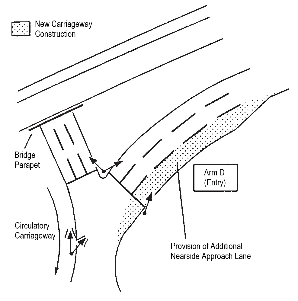
NOTE 2 CD 123 [Ref 3.N] provides requirements and advice for direct tapers, where they are provided, and storage lengths for additional approach lanes.
General geometry at signal-controlled roundabouts
Traffic islands
4.4 On signal-controlled roundabouts, where dedicated left turn lanes are provided, traffic islands shall be used to separate uncontrolled traffic from controlled traffic, as shown in Figure 4.4.

4.4.1 Traffic islands may be provided in other situations to separate two independently controlled lanes of traffic on the same roundabout entry or on the circulatory carriageway of a grade separated roundabout.
Entries
4.5 Give way markings shall not be provided at any entries with direct full-time signal-control.
NOTE Give way markings can be used at any entries where there is indirect part-time or full-time signal-control.
Swept path
4.6 The design of a signal-controlled roundabout shall allow for the swept paths of the design vehicle on all entry, circulatory and exit lanes, including all through lanes across the central island of a through-about.
NOTE The nature of the signal-controlled roundabout and its associated traffic islands and pedestrian refuges can restrict the movement of vehicles, particularly HGVs.
Visibility of signals
4.7 On an external approach to a signal-controlled roundabout, each traffic lane shall have clear visibility of at least one primary traffic signal associated with its particular movement, from a distance equivalent to the desirable minimum SSD of the approach road.
NOTE 1 Requirements and advice for visibility on the circulatory carriageway are provided in Section 3, "Circulatory visibility".
NOTE 2 Requirements and advice on the provision of additional signal heads are provided in CD 123 [Ref 3.N].
4.8 Visibility to the primary signal on an external approach to a signal-controlled roundabout shall be in accordance with the CD 109 [Ref 4.N] visibility envelope, but with the high object height amended to incorporate the signal head where this exceeds 2 metres, as indicated in Figure 4.8.
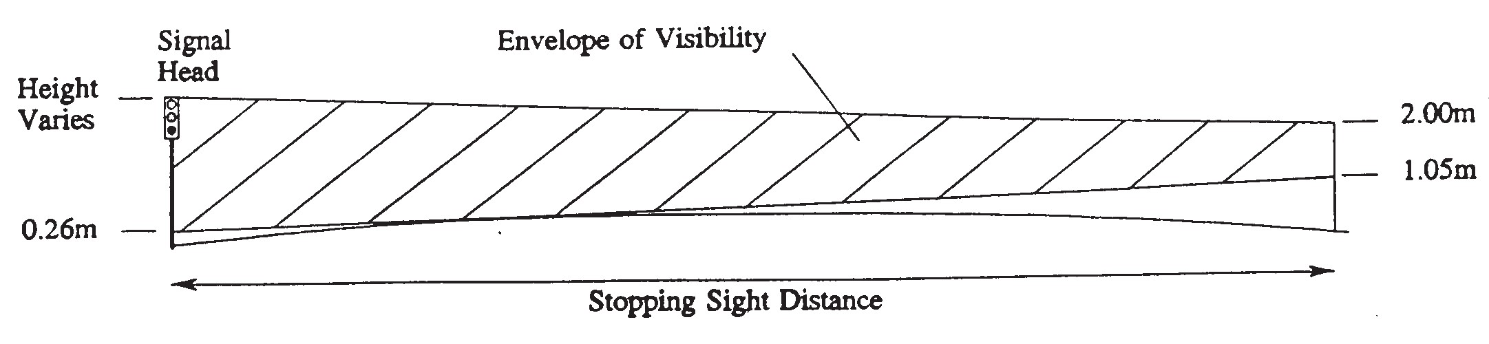
Junction intervisibility zone
4.9 All internal and external approaches on roundabouts that operate under signal-control at any time shall be provided with an intervisibility zone which extends across the full carriageway width of each arm from a distance of 2.5 metres back from each stop line.
4.9.1 For signal-controlled roundabouts the junction intervisibility zone on the circulatory carriageway should be measured to a point 2.5 metres beyond the secondary signal, as illustrated on Figure 4.9.1.
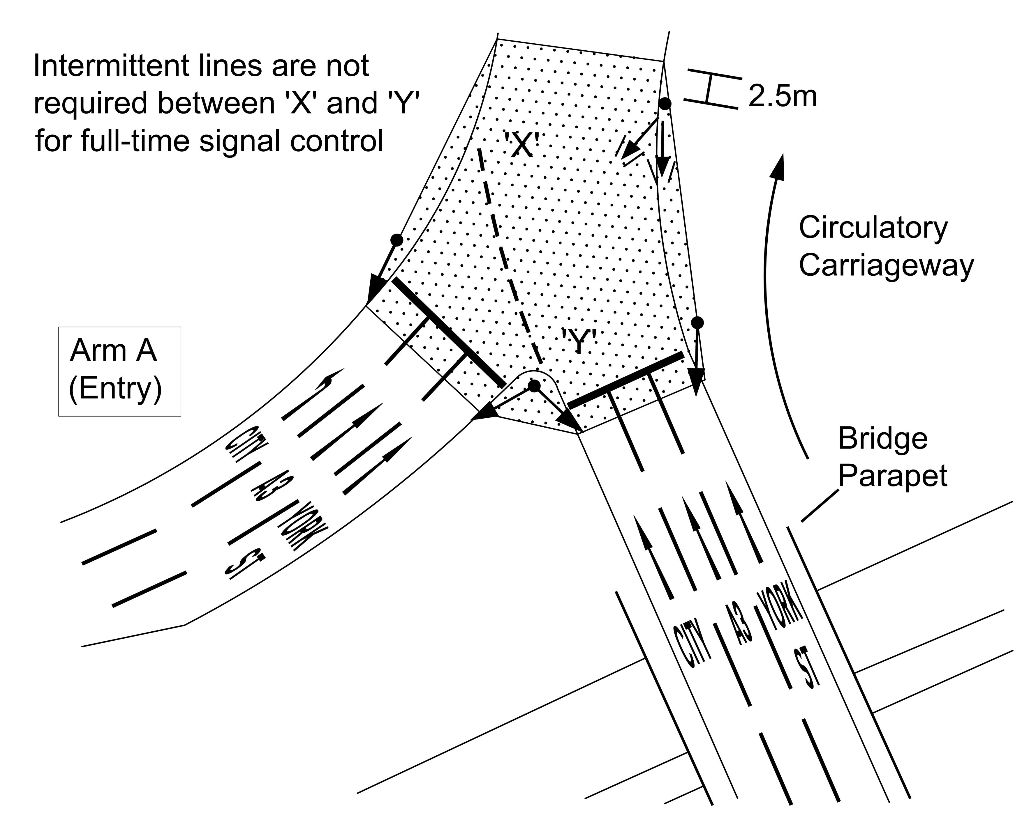
4.10 Where an advance stop line (ASL) is provided on a roundabout approach, the intervisibility zone shall be measured from a point 2.5 metres behind the cycle stop line.
NOTE The intervisibility zone is measured from a point 2.5 metres behind the cyclists’ stop line because the cycle reservoir behind the ASL does not create any physical impediment to intervisibility.
4.10.1 Where there is a pedestrian crossing adjacent to a stop line, the junction intervisibility should be extended to ensure that drivers of all vehicles on each entry lane are able to see the full extent of the pedestrian crossing (and its approach).
4.10.2 The junction intervisibility at a pedestrian crossing should include the full width of the strip of tactile paving laid parallel to the edge of carriageway.
NOTE Further requirements and advice on the provision and intervisibility of pedestrian crossings adjacent to a signal-controlled junction are provided in CD 123 [Ref 3.N].
4.11 No substantial fixed obstructions shall be located within the intervisibility zone of new roundabouts.
NOTE Details of what constitutes a substantial fixed obstruction are provided in CD 109 [Ref 4.N].
4.11.1 No substantial fixed obstructions should be located within the intervisibility zone of existing roundabouts.
5. Design of mini-roundabouts
Geometric design of a mini-roundabout
5.1 The maximum ICD of a mini-roundabout shall be 28 metres.
NOTE Main requirements and advice for the geometric design of all roundabouts are provided in Section 3.
5.1.1 For mini-roundabouts with two entry lanes the width of the circulatory carriageway should enable cars to travel two abreast around the white circle.
Mini-roundabout central islands
5.2 The white circle of a mini-roundabout shall have a maximum of 4 metres diameter and positioned using the inside of the swept path of cars.
NOTE A mini-roundabout does not have a kerbed central island. In its place is a flush or domed circular solid white road marking capable of being driven over where unavoidable by large vehicles or where the layout of the junction makes it impractical to do so. The circular marking can be edged with kerbs provided the maximum height above the road surface at the perimeter does not exceed 6 mm.
5.2.1 Where a white circle with a full diameter of 4 metres is not achievable on a mini-roundabout, a white circle with a diameter as large as possible between 1 metre and 4 metres should be provided.
NOTE A larger diameter up to the maximum 4 metres can improve conspicuousness of the central marking.
5.3 Additional circular rings shall not be added around the white circle of a mini-roundabout.
5.4 The centre of the design vehicle path shall be at least 1 metre from kerbs, the perimeter of the white circle, and from any road marking separating opposing traffic.
NOTE Figures 5.4Na and 5.4Nb provide examples of how the design vehicle path and white circle location of a mini-roundabout are determined using swept paths.

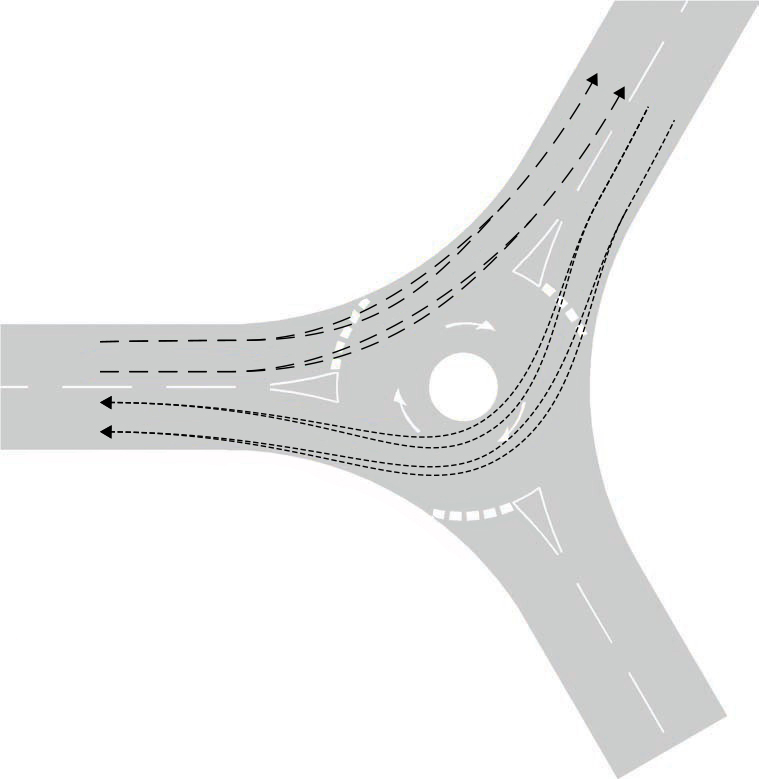
5.4.1 The white circle of a mini-roundabout should be sized and located so that drivers of cars are not encouraged to drive on it or pass on the wrong side of it when negotiating the junction.
5.5 For a right-turn design vehicle path on a mini-roundabout, a minimum design vehicle path radius of 6 metres, at the centre of the path, shall be used.
5.5.1 For the right turn minimum design vehicle path radius of 6 metres, the vehicle path should be widened to 3 metres at the apex of the turn.
5.6 The height of the dome of the white circle above the adjacent carriageway must be no greater than 125 mm at its highest point (including construction tolerance) (in accordance with UKSI 2016/362 (TSRGD) [Ref 9.N]Schedule 9 Part 8 Paragraph 4).
NOTE A domed white circle marking can be used to deter light vehicles from overrunning and improve its conspicuousness. The dome can normally be formed from bituminous material, concrete or block paving.
5.6.1 The white circle for a 4-metre diameter marking should be domed to a recommended height at the centre of 100 mm.
5.6.2 For smaller diameter markings the height of the dome should be reduced pro rata (i.e. by 25 mm per metre width of the white circle diameter).
5.6.3 A domed white circle should be avoided for mini-roundabouts regularly overrun by heavy goods vehicles or buses in residential areas.
NOTE The use of a domed white circle can lead to the perception of vibration by residents and discomfort to bus drivers and passengers.
5.6.4 Fire and ambulance services should be consulted about any proposal to introduce a mini-roundabout with a domed white circle.
5.7 The height of the white dome at its perimeter shall not exceed 6mm.
Overrun areas
5.8 The design of overrun areas must be in accordance with UKSI 1999/1026 [Ref 8.N].
5.9 The diameter of a mini-roundabout overrun area shall not exceed 7.5 metres, including the white circle.
NOTE An example of a mini-roundabout overrun area is shown in Figure 5.9N.
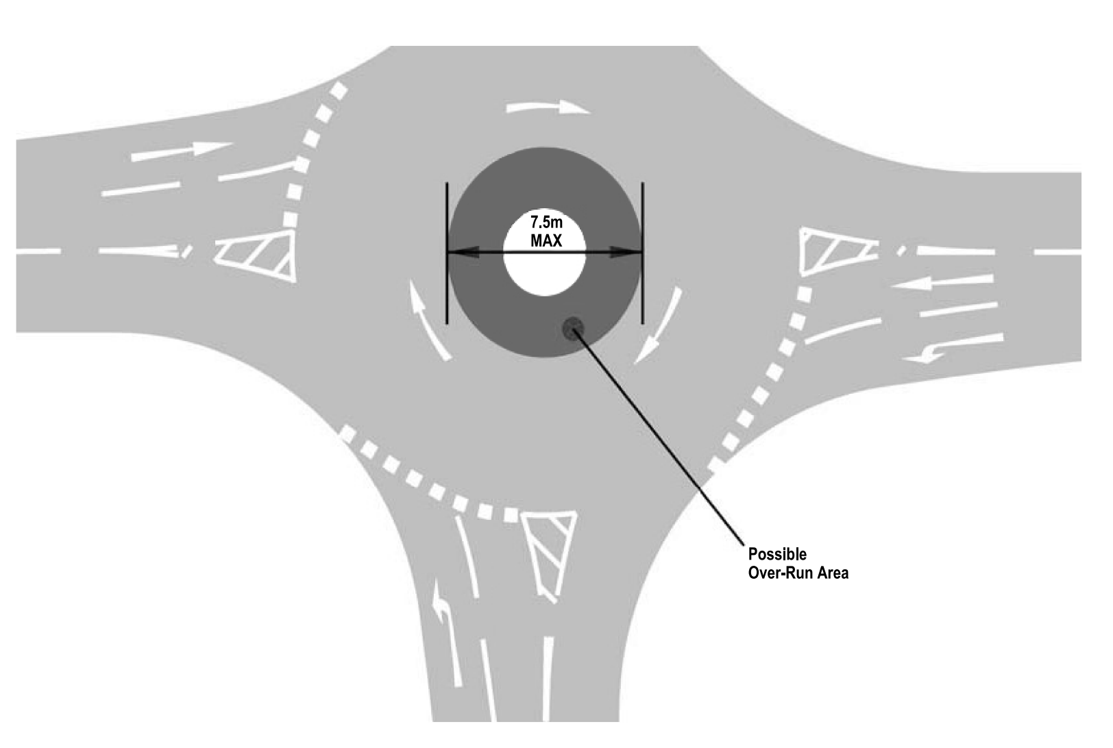
5.9.1 A concentric overrun area may be used on a mini-roundabout to increase the deflection and it's conspicuousness.
NOTE Light vehicles are not legally obliged to avoid overrun areas in the same way as the white circle of a mini-roundabout and therefore concentric overrun areas cannot be relied upon for the purposes of achieving deflection.
5.10 Additional road markings shall not be placed on or around the edges of a concentric overrun area.
5.10.1 The circulatory arrow markings of a mini-roundabout should be placed on the surrounding circulating area and not on the overrun area.
Mini-roundabout traffic islands
5.11 Where vehicles can pass on the wrong side of the white circle on a mini-roundabout, a kerbed traffic island shall be provided on the arms of a junction.
5.11.1 Traffic islands may be provided to separate opposing streams of traffic and, where appropriate, to serve one or more of the following purposes:
- assist provision of deflection of the path of vehicles approaching the mini-roundabout;
- increased conspicuousness for drivers approaching the mini-roundabout;
- pedestrian use; or
- calming feature.
5.11.2 Islands for separating opposing streams of traffic or deflecting approaching vehicles may be kerbed physical islands or created using road markings prescribed in UKSI 2016/362 (TSRGD) [Ref 9.N].
5.11.3 A kerbed island may be used at an entry to accommodate bollards and supplementary signs.
NOTE Requirements and guidance on the appropriate signage for a mini-roundabout are provided in UKSI 2016/362 (TSRGD) [Ref 9.N] and TSM Chapter 3 [Ref 12.N].
5.11.4 Any sign on a kerbed island should not restrict visibility to the right.
5.11.5 Kerbed islands designed to narrow the carriageway within 40 metres of the give way line of a mini-roundabout may be used as a calming feature to control the speed of approaching traffic.
NOTE Guidance on the use of islands to narrow the carriageway is contained in TAL 7/95 [Ref 18.I].
5.12 A kerbed island shall be positioned at least 0.5 metres clear of any vehicle swept path.
5.13 Solid or raised areas of markings shall not be used at mini-roundabouts, other than for the white circle.
Mini-roundabout entry width
5.14 For a single lane approach on a mini-roundabout, the lane width at the give way line shall be no less than 3 metres and no greater than 4 metres.
5.14.1 For a two lane approach on a mini-roundabout, the minimum lane width at the give way line may be reduced to 2.5 metres, provided heavy goods vehicles and buses do not frequently use the entry.
5.15 At an entry with multiple lanes on a mini-roundabout, no more than one lane shall be marked as being for a given exit arm.
NOTE Markings are provided such that traffic going ahead or turning proceeds in single file for each movement.
5.15.1 Three lane entries should not be used for mini-roundabouts.
NOTE 1 The presence of two or more approach lanes encourages two abreast flow through the mini-roundabout, increasing the number of potential conflicts. Additional signing and marking can be used where entries are divided into multiple lanes to ensure safe and efficient operation.
NOTE 2 Where a three-arm mini-roundabout with single lane approaches replaces a major/minor priority junction, the junction becomes easier to negotiate, as drivers only have to concentrate on one stream of traffic circulating at low speed from their right. However, as the number of arms and/or traffic lanes to the mini-roundabout increases, so does the potential for conflict.
5.16 No more than two lanes shall be provided at an intermediate give way line between double mini-roundabouts.
5.16.1 On a double mini-roundabout, the short link between the two roundabouts should provide space for vehicles waiting at the intermediate give way lines, as illustrated in Figure 5.16.1.
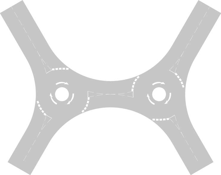
NOTE 1 Where the link between the two roundabouts is not adequately sized, large opposing right-turning movements can lead to gridlock at double mini-roundabouts, particularly if the network is congested.
NOTE 2 The capacity at an intermediate give way line between double mini-roundabouts can be reduced by the effect of the first junction, and a queue at the intermediate give way line can interact with the first junction. Double junctions with short links of only one or two car lengths can be more susceptible to queuing than those with greater separation.
Mini-roundabout exit width
5.17 On mini-roundabouts, the exit width shall be measured as the distance between the nearside kerb and exit median (or the edge of any traffic island) where it intersects with the outer edge of the circulatory carriageway.
Deflection
5.18 Deflection or other means of slowing vehicles on approach to the give way stop line shall be provided on a mini-roundabout.
NOTE 1 Other means of slowing vehicles include additional signage or narrowing of approach.
NOTE 2 Both the speed and path of a vehicle through a mini-roundabout are important factors in accident causation. Adequate deflection allows the approaching drivers to be aware of the circulatory nature of the junction ahead. Drivers need to be ready to stop if necessary on the approach so it is essential for entry (and circulatory) speeds to be managed by careful design.
NOTE 3 Where vehicle speeds are already low on mini-roundabouts, full entry deflection as required for normal or compact roundabouts is not essential.
NOTE 4 The introduction of some entry deflection on entry to the mini-roundabout helps to induce gyratory movement and increase efficiency.
5.18.1 A lateral shift (see Figure 5.18.3) of 0.8 metres minimum should be provided at entry.
NOTE The value of 0.8 metres for lateral shift corresponds to the minimum width required to accommodate hatched road marking to UKSI 2016/362 (TSRGD) [Ref 9.N] diagram 1040 (Schedule 11 Part 4 Item 23). These markings are used to separate opposing traffic flows and further details can be found in UKSI 2016/362 (TSRGD) [Ref 9.N] (Schedule 11 Part 3) and TSM Chapter 5 [Ref 14.N].
5.18.2 Deflection (or lateral shift) should be introduced on the offside of the approach arm.
5.18.3 For offside shift, the lateral shift should be measured from the centre of the approach road, developed at a rate 1 in 7.5 as shown in Figure 5.18.3 Example A.
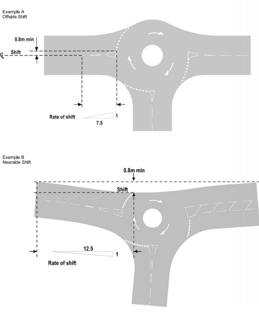
5.18.4 Where there are constraints (for example, land restrictions, structural obstructions, environmental features) at a mini-roundabout, an alternative method, known as 'nearside shift' and illustrated in Figure 5.18.3 example B, may be used to develop shift along the nearside carriageway edge.
NOTE Nearside shift can be an effective way of introducing deflection in order to encourage low entry speeds. However, nearside shift can have the effect of deflecting traffic to the right, towards the central island, and is therefore often less effective in inducing a gyratory movement than offside shift. For this reason, nearside shift is deemed to be less desirable than offside shift.
5.18.5 For nearside shift, the lateral shift should be measured from the nearside edge of the approach road, developed at a rate 1 in 12.5, as illustrated in Figure 5.18.3 Example B.
5.18.6 Mandatory give way signs and markings to UKSI 2016/362 (TSRGD) [Ref 9.N] diagram 602 (Schedule 9 Part 2 Item 2), diagram 1003 (Schedule 9 Part 6 Items 3 and 9) and diagram 1023A (Schedule 9 Part 6 Item 4) should only be used on the approach to a three-arm mini-roundabout where there is another entry to the right but none to the left as shown in Figure 5.21 and in accordance with TSM Chapter 3 [Ref 12.N] and TSM Chapter 5 [Ref 14.N].
NOTE The use of give way signs and markings in other situations can confuse drivers as to who has priority and undermines the priority rule established for mini-roundabouts.
5.18.7 Where the lateral shift cannot be achieved or visibility to the right is limited, mandatory give way signs and markings to UKSI 2016/362 (TSRGD) [Ref 9.N] diagram 602 (Schedule 9 Part 2 Item 2), diagram 1003 (Schedule 9 Part 6 Items 3 and 9) and diagram 1023A (Schedule 9 Part 6 Item 4) may be used on the approach.
5.18.8 Where the give way sign is co-located with the mini-roundabout regulatory sign, the give way sign should be uppermost.
NOTE Further guidance on the classification of signs is provided in TSM Chapter 1 [Ref 11.N].
5.18.9 On a mini-roundabout where sufficient entry deflection of vehicle paths is not achieved by road markings, islands and existing kerbs, a reduction in vehicle speeds may be achieved by narrowing the approach.
5.18.10 On a mini-roundabout, overrun areas may be utilised instead of narrowing the approach, if narrowing the approach arm affects the swept path of long vehicles on the nearside of an entry.
5.19 Any vertical deflection for traffic calming at a mini-roundabout shall take the form of a speed table with the following requirements:
- the top of the speed table covers the whole junction area; and
- extends outwards a minimum of 6 metres upstream of each give way line.
Crossfall on a mini-roundabout
5.20 The design of crossfalls and gradients at mini-roundabouts shall not result in ponding of surface water within the roundabout carriageway including on and around the central white circle.
5.20.1 Gullies should not be installed adjacent to the white circle to drain ponding or accumulated run-off.
5.20.2 Where a mini-roundabout is constructed at the location of a former priority junction, channels, which can give the impression of a former priority junction layout, should be eliminated.
NOTE Mini-roundabouts have often been superimposed on the existing carriageway profile with little or no change in level.
5.20.3 Where the carriageway levels are re-profiled, crossfall should be outward sloping to avoid ponding and improve junction conspicuousness.
Mini-roundabout visibility
5.21 A minimum visibility distance ‘D’, as shown in Figure 5.21 and in accordance with Table 5.21, shall be the minimum sight distance required at a distance ‘F’ from the give way line in relation to the approach speed of the arm.
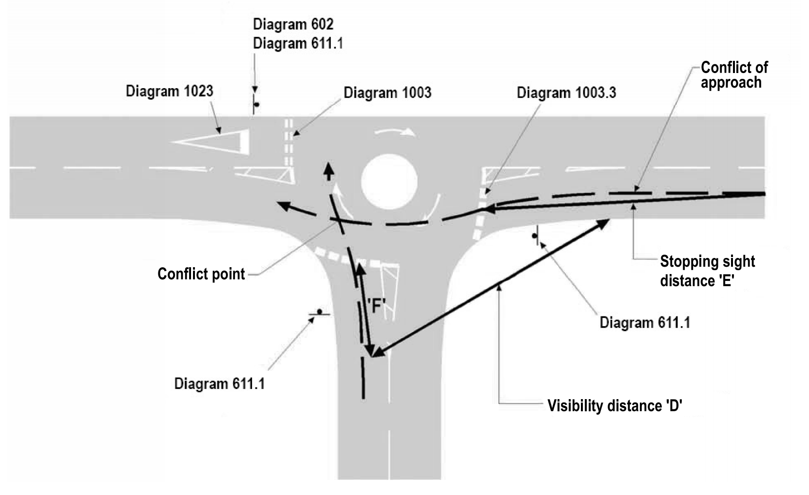
| 85th percentile speed of arm to the right (mph) | 'D' distance (metres) | |
|---|---|---|
| For a gap acceptance time of two seconds | For a gap acceptance time of three seconds | |
| 35 | 40 | 55 |
| 30 | 35 | 50 |
| 25 | 25 | 40 |
NOTE 1 ‘D’ is measured from the centre of the offside approach lane to the nearside carriageway edge of the arm to the right.
NOTE 2 Distance ‘D’ varies with the 85th percentile approach speed 70 metres before the give way line on the arm to the right and the ‘gap acceptance time’.
NOTE 3 The 'gap acceptance time' is dependent on the size of the roundabout, it is two seconds when the distance from the give way line to the centre of the white circle is 7.0 metres or less, otherwise it is three seconds.
5.22 The visibility distance ‘D’ shall be unobstructed between driver’s eye heights of 1.05 metres and 2.0 metres at the centre of the offside approach lane to object heights between 0.26 metres and 2.0 metres at the nearside edge of the arm to the right.
5.23 The SSD on the approach to a mini-roundabout (illustrated as ‘E’ in Figure 5.21) shall be provided in accordance with Table 5.23.
| 85th percentile speed (mph) | Minimum 'E' distance (metre) |
|---|---|
| 35 | 80 |
| 30 | 70 |
| 25 | 50 |
5.24 The SSD on the approach to a mini-roundabout shall be provided within the whole of an envelope between eye heights of 1.05 metres and 2.0 metres at the centre of the path of an approaching vehicle to object heights of 0.26 metres to 2.0 metres at the give way line.
5.25 The minimum ‘F’ distance in Figure 5.21 shall be 9.0 metres, except in the following circumstances:
- where the 9.0 metres cannot be achieved, the 'F' distance on an arm can be reduced to 4.5 metres, providing that the maximum peak hour entry flow on the arm is less than 300 veh/hr; or
- where neither the 9.0 metres or the relaxed minimum 'F' distance of 4.5 metres can be achieved, the ‘F’ distance for an arm can be reduced to 2.4 metres, providing that the maximum peak hour entry flow on the arm is less than 300 veh/hr and where there is no entry arm to the left.
NOTE 1 A minimum 'F' distance of 9.0 metres is provided so that the first two vehicles in the approach queue have visibility of traffic coming from the arm on the right.
NOTE 2 'F' distances significantly greater than 9.0 metres can result in high approach speeds. Consider limiting the visibility to the right of adjacent entries to a maximum ‘F’ distance of 15 metres back on the approach and to no more than the ‘D’ distance.
NOTE 3 Excessive visibility between adjacent entries can result in approach and entry speeds greater than desirable for the junction geometry, with a tendency for approaching drivers to take a decision too early about whether to give way, particularly in locations with low turning movements. Road users approaching a mini-roundabout need to be able to stop if vehicles are circulating or if there is an obstruction on the junction. There is little or no advantage in increasing the ‘D’ distance as this could lead to excessive approach speeds.
NOTE 4 An 'F' dimension of 2.4 metres enables a road user who has reached the give way line to see approaching vehicles without encroaching past the give way line.
NOTE 5 An 'F' dimension of 2.4 metres can, however, allow only one vehicle at a time to enter safely and requires following drivers to be prepared to stop and look.
5.26 Where 'F' dimension of 2.4 metres is used, the mandatory give way markings and upright sign must be in accordance with UKSI 2016/362 (TSRGD) [Ref 9.N] diagram 1003 (Schedule 9 Part 6 Items 3 and 9), diagram 1023A (Schedule 9, Part 6 Item 4) and diagram 602 (Schedule 9 Part 2 Item 2) to require road users to give way to circulating traffic at the give way line.
Additional signs and markings requirements and advice for mini-roundabouts
5.27 Where the give way sign UKSI 2016/362 (TSRGD) [Ref 9.N] diagram 602 (Schedule 9 Part 2 Item 2) is used, it must be accompanied by the approach to a road junction triangle symbol UKSI 2016/362 (TSRGD) [Ref 9.N] diagram 1023A (Schedule 9 Part 6, Item 4) and by the give way marking to UKSI 2016/362 (TSRGD) [Ref 9.N] diagram 1003 (Schedule 9 Part 6 Items 3 and 9).
5.28 Where the swept path of the largest vehicle anticipated to use the junction crosses the inscribed circle, the give way markings for the affected arms shall be moved back such that they are not crossed by the outside edge of the swept path.
NOTE The largest vehicle anticipated circulating past the entry is used for swept path analysis.
5.28.1 Where mandatory give way markings (to UKSI 2016/362 (TSRGD) [Ref 9.N] diagram 1003 (Schedule 9 Part 6 Items 3 and 9)) are used at a mini-roundabout, they should be placed in a straight line at right angles to the vehicle path with no part of the marking inside the outer edge of the swept path.
NOTE Typically, the give way line to UKSI 2016/362 (TSRGD) [Ref 9.N] diagram 1003.3 (Schedule 9 Part 6 Items 3 and 9) is placed on the circumference of the largest circle that can be inscribed within the junction kerbs.
5.28.2 Where the regulatory sign to UKSI 2016/362 (TSRGD) [Ref 9.N] diagram 611.1 (Schedule 9 Part 2 Item 6) is not visible from 50 metres before the give way line or is not conspicuous, an additional sign to UKSI 2016/362 (TSRGD) [Ref 9.N] diagram 611.1 (Schedule 9 Part 2 Items 6) should be provided on a kerbed traffic island, together with the mandatory give way sign in accordance with UKSI 2016/362 (TSRGD) [Ref 9.N].
5.28.3 A roundabout warning sign to UKSI 2016/362 (TSRGD) [Ref 9.N] diagram 510 (Schedule 2 Part 2 Item 7) should be provided where the visibility distance to the mini-roundabout regulatory sign (diagram 611.1 (Schedule 9 Part 2 Item 6)) is less than 50 metres and an advance direction sign does not precede the junction.
NOTE Guidance on the design of the ADS is given in TSM Chapter 7 [Ref 16.N].
5.29 The prescribed mini-roundabout markings must be in accordance with UKSI 2016/362 (TSRGD) [Ref 9.N] diagram 1003.4 (Schedule 9 Part 6 Item 5).
5.29.1 The domed white circle should be formed and maintained in white reflectorised materials that provide a clear and durable contrast with the adjacent surface in all conditions.
5.30 Where the white circle is to be edged, only kerbing or edging block of uniform shape shall be used.
5.30.1 Kerbing or edging block of uniform shape with an even surface may be used to contain the white circle provided that it is reflectorised, the maximum height above the road surface at the perimeter does not exceed 6mm and the appearance of the marking is in accordance with UKSI 2016/362 (TSRGD) [Ref 9.N] diagram 1003.4 (Schedule 9 Part 6 Item 5).
NOTE Types of white circle edging, other than kerbing and edge blocks, can be a hazard, particularly to cyclists.
5.31 Warning lines must be provided on the approaches to kerbed physical islands in accordance with UKSI 2016/362 (TSRGD) [Ref 9.N] diagram 1004 (Schedule 11 Part 4 Item 2) and TSM Chapter 5 [Ref 14.N].
5.31.1 The conspicuousness of a mini-roundabout should not rely solely on road markings, which can become worn or less conspicuous in the wet or in adverse lighting conditions.
NOTE Where a build-out is provided, its conspicuousness and that of the junction as a whole can be enhanced if vertical features such as bollards, directional or regulatory signs can safely be located on the build-out while not obstructing the highway / road.
5.31.2 The use of yellow backing boards for a mini-roundabout scheme should be reserved for identified problems of road users not seeing the sign in sufficient time, or not seeing it at all.
NOTE Further guidance on the use of backing boards is provided in TSM Chapter 7 [Ref 16.N].
5.31.3 The use of grey backing boards may be appropriate for enhancing the conspicuousness of the mini-roundabout regulatory sign or where a give way sign to UKSI 2016/362 (TSRGD) [Ref 9.N] diagram 602 (Schedule 9 Part 2 Item 2) is to be co-located with it.
5.31.4 Rather than applying backing boards, a larger size of sign may be used to improve the conspicuousness of the sign.
5.31.5 When using coloured surfacing as a remedial measure to improve the conspicuousness of a mini-roundabout, the level of contrast between the road markings and adjacent coloured surfacing should be assessed.
5.31.6 Coloured surfacing should not be laid in any shape or pattern intended to convey a meaning as a road marking on a mini-roundabout.
6. Design of segregated left turn lanes and segregated lanes
Inclusion of a segregated left turn lane and segregated lane
6.1 The following initial assessment shall be undertaken when determining whether to provide a segregated left turn lane (SLTL) or segregated lane: L ≥ F / E
- L is the flow in vehicles per hour taking the first exit;
- F is the total entry arm inflow in vehicles per hour for the arm being determined;
- E is the number of proposed entry lanes onto the roundabout including the SLTL or segregated lane.
NOTE 1 Appendix C provides a decision process for the inclusion of an SLTL.
NOTE 2 Main requirements and advice for the geometric design of all roundabouts are provided in Section 3.
6.1.1 The initial assessment should:
- typically include AM and PM peak hour traffic flows (including for peak commuter and development usage);
- also include an assessment of forecast traffic flows to make allowances for background traffic growth and any nearby future development that could affect the junction.
6.1.2 Even if a peak period review satisfies the initial assessment formula, the design should further assess off-peak flows to ensure that any potential dis-benefits in the off-peak periods do not outweigh peak hour benefits (e.g. reduced capacity at the give way line).
6.1.3 The results of any assessment outlined should show that the provision of an SLTL or segregated lane is the most appropriate form of improvement, compared with alternatives such as modifications to flare lengths or entry widths or traffic signal-control.
6.1.4 Where the value of F/E is above but close to L, the provision of an SLTL or segregated lane should be further assessed, taking into account other factors such as potential road safety benefits.
6.1.5 To assess the full impacts of a SLTL or a segregated lane a traffic micro-simulation or similar technique should be used.
6.1.6 An SLTL should only be implemented if:
- it increases the overall capacity of the junction, to a greater extent than other designs; or
- it improves road safety of the junction i.e. reduction in collision numbers or severity; and
- it safely accommodates WCHR (at locations where they are legally permitted).
6.1.7 Where flows taking the first exit are greater than 1,500 vehicles per hour, alternative junction forms or methods of junction control should be used.
6.2 SLTLs and segregated lanes shall consist of one lane only.
NOTE Two lane SLTLs and segregated lanes can result in high vehicle speeds and potential conflict at the diverge and merge point for the SLTL or segregated lane.
6.2.1 On an SLTL, where physical segregation is introduced, this should allow a left turn at the roundabout in the normal way from the non-segregated part of the approach as shown in Figure 6.2.1.
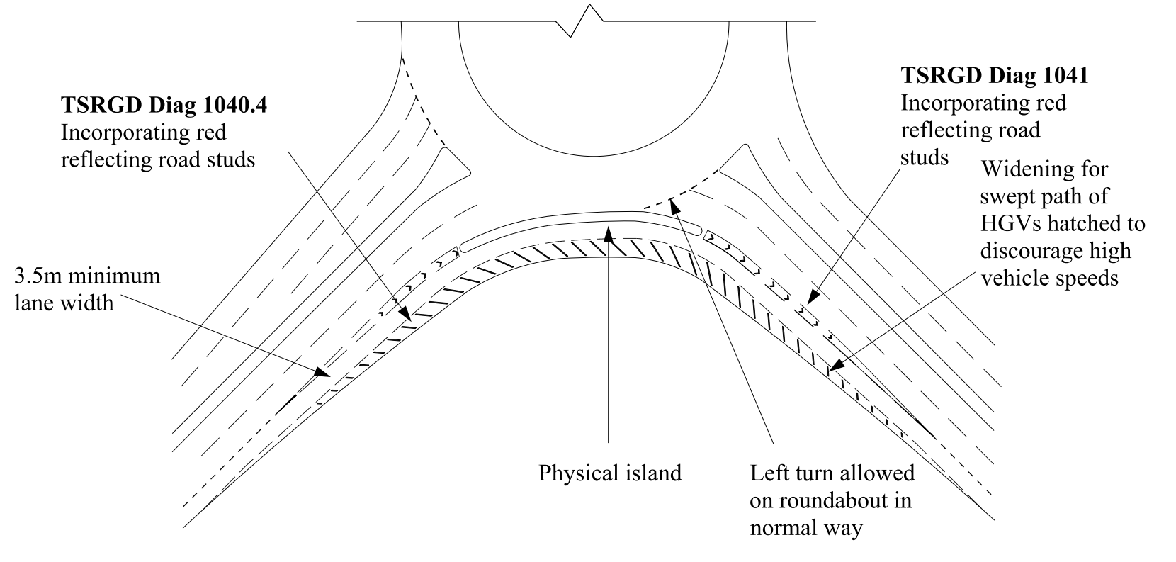
6.2.2 SLTLs should not be designed to induce high vehicle speeds.
NOTE Designing to the geometric requirements and advice of this section can help avoid inducing high vehicle speeds.
6.2.3 Where there is a need to reduce vehicle speeds at an SLTL, this should be achieved on the approach to the SLTL rather than within it.
General design requirements for a segregated left turn lane
General
6.3 Accesses, junctions, lay-bys and bus stops shall not be located within SLTLs.
6.4 Uncontrolled crossing points shall not be provided across SLTLs.
NOTE Advice on provisions for pedestrians and cyclists is given in Section 8 of this document.
6.4.1 Where there is demand for WCHR facilities, SLTLs should only be provided if WCHRs can be catered for safely within the junction design.
Physical segregated left turn lanes
6.5 At signalised roundabouts any SLTL shall be physically separated from the circulatory carriageway and adjacent entry and exit arms with kerbed islands.
6.6 Physical SLTLs shall only be provided at street lit junctions.
6.7 Physical SLTLs shall be used where vehicles using the SLTL have to give way at the exit.
6.8 Where the SLTL is situated on an abnormal load route, the use of a physical segregated left turn island shall be assessed to demonstrate sufficient swept path width is provided for the abnormal load vehicle anticipated to use the SLTL.
6.8.1 Where sufficient carriageway width cannot be provided between kerbs, a non-physical SLTL island should be assessed for implementation providing that other conditions laid down in Figure C.1 and requirements elsewhere within this document are met.
Non-physical segregated left turn lanes
6.9 Non-physical SLTLs shall only be used on sections of highway / road where crossing facilities for WCHRs are provided away from the SLTL or where WCHR facilities are not required.
6.9.1 A physical island should be provided in preference to a non-physical SLTL.
NOTE 1 Non-physical SLTLs can be subject to abuse by drivers crossing the hatched island area resulting in conflicts in the vicinity of the SLTL.
NOTE 2 The effectiveness of a non-physical island incorporated in a SLTL layout can be enhanced through the use of continuous, rather than broken, road markings (to UKSI 2016/362 (TSRGD) [Ref 9.N] diagram 1042 (Schedule 9 Part 6 Item 22)), coloured surfacing and enhanced road marking materials that provide improved performance during the hours of darkness and in inclement weather.
6.9.2 Raised or domed surfaces, flush kerbs or infilling with marking material to reinforce road markings should not be used (with the exception of coloured infill surfacing) on a non-physical left turn lane.
General design requirements for segregated lanes for straight ahead traffic movements
6.10 A segregated lane for straight ahead traffic movements shall only be provided for the first exit at a three arm roundabout or on roundabouts with four or more arms that are asymmetrically arranged.
6.10.1 An alternative layout should be provided if the design of segregated lanes for straight ahead traffic movements cannot be:
- designed to not have high entry speeds;
- designed without the use of reverse curves both on the approach and through the roundabout and abrupt changes in crossfall;
- designed in conjunction with achieving the entry path radius requirements and advice;
- designed to accommodate the safe crossing movements of WCHRs (where the need for WCHR facilities is identified); and,
- designed to not have significant differential exit speeds from the straight ahead segregated lane compared to vehicles leaving the roundabout circulatory carriageway.
NOTE 1 Where there are higher speed of vehicles exiting the straight ahead lane compared with slower traffic leaving the roundabout circulatory carriageway can result in merging problems.
NOTE 2 Entry path radius requirements are provided in Section 3.
Geometric requirements for segregated left turn lanes
General segregated left turn lanes geometric requirements
6.11 On an SLTL, nearside curve radii shall be 10 metres or greater.
NOTE The curve radius used for the SLTL is dependent on both the design speed of the approach road and site constraints.
6.11.1 The need for speed reduction measures on the approach to an SLTL should be based on the minimum curve radii used in relation to the approach speed.
NOTE The driver’s perception of the approach and SLTL radii is a determining factor in their approach speed.
6.12 On an SLTL, the exit radius used shall be greater than, or equal to, the entry radius used in the design of the SLTL.
6.13 The carriageway widths given in Table 6.13 shall be used on an SLTL based on the minimum curve radius on the entry or exit.
| Minimum nearside kerb radius (metres) (1) |
SLTL carriageway width (for island lengths <50 metres) (metres) (2) |
SLTL carriageway width (for island lengths >50 metres) (metres) (3) |
|---|---|---|
| 10 | 8.4 | 10.9 |
| 15 | 7.1 | 9.6 |
| 20 | 6.2 | 8.7 |
| 25 | 5.7 | 8.2 |
| 30 | 5.3 | 7.8 |
| 40 | 4.7 | 7.2 |
| 50 | 4.4 | 6.9 |
| 75 | 4.0 | 6.5 |
| 100 | 3.8 | 6.3 |
| >100 | 3.5 | 6.0 |
NOTE Carriageway widths in Table 6.13 are inclusive of the 0.3 metres marking offset from kerbs.
6.14 A maximum value of 5% superelevation shall be applied along an SLTL.
NOTE Further requirements and advice on superelevation are provided in CD 109 [Ref 4.N].
6.15 Hatched road markings shall be provided on the nearside of the curve to retain a marked lane width of a minimum of 3.5 metres as shown in the indicative cross-section in Figure 6.15 (for a an SLTL island less than 50 metres in length and with a nearside kerb radius of 20 metres).
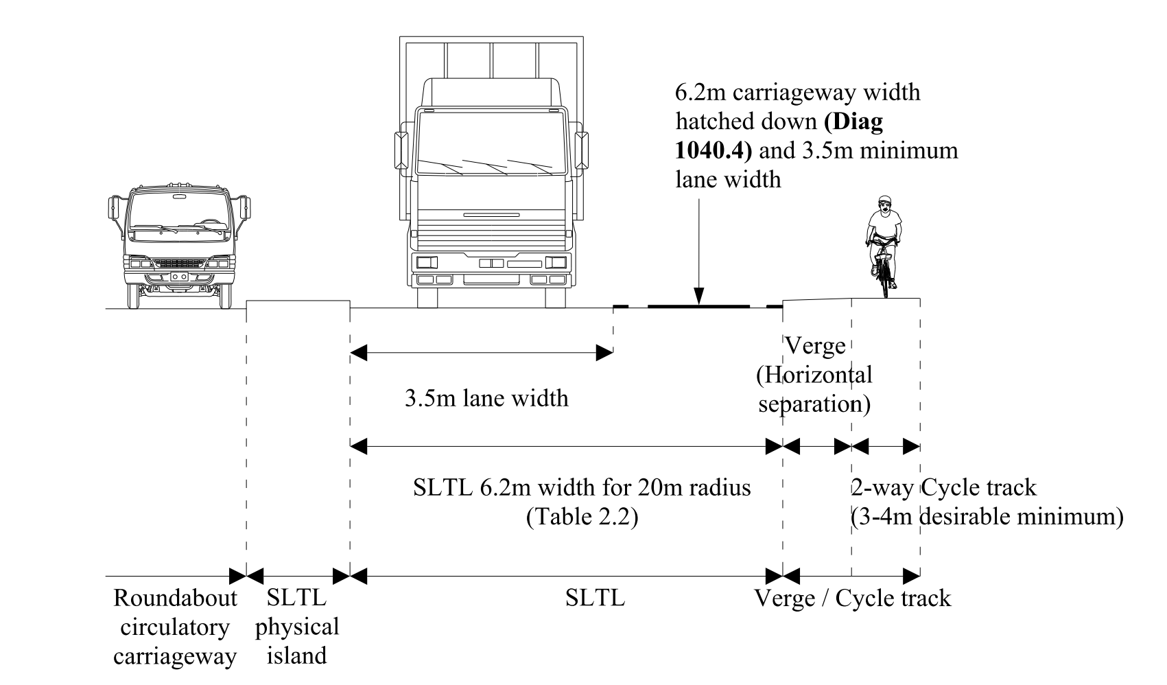
NOTE Refer to Table 6.13 for different carriageway width requirements based on SLTL island length and the nearside kerb radius.
6.16 Hard strips shall be terminated at the start of the entry taper and commence at the end of the exit taper as shown on Figure 6.16.
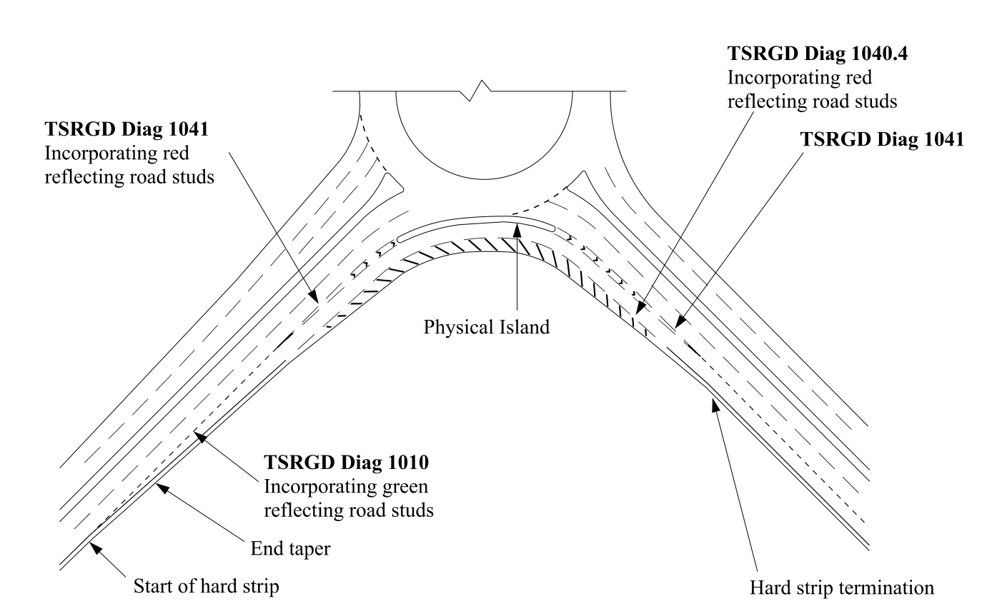
6.17 Where hatched road markings are provided on the inside of the SLTL, the hard strip shall form the start of the hatching.
6.18 Physical islands shall be a minimum width of 1.6 metres.
NOTE Requirements for pedestrian and cycle traffic at physical islands are provided in Section 8 of this document.
6.19 Where road markings are used to create the lane segregation, the overall width of the marked island shall be a minimum of 1 metre.
6.20 Where WCHRs are prohibited from crossing the SLTL the physical island shall extend a minimum of 1.5 metres and 6 metres into the entry and exit roads respectively beyond the traffic islands, as shown on Figure 6.20.
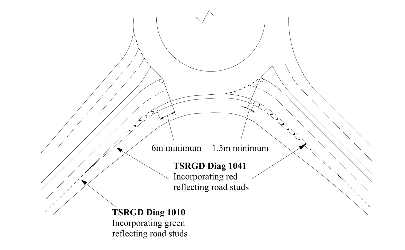
6.21 Where WCHRs are permitted and therefore crossing facilities are provided adjacent to the roundabout entry or exit, the physical island shall extend a minimum length of 2.5 metres on both the entry and exit beyond the crossing point as shown on Figure 6.21.

6.22 Non-physical islands shall start and finish at the entry and exit road limits respectively as shown on Figure 6.22.
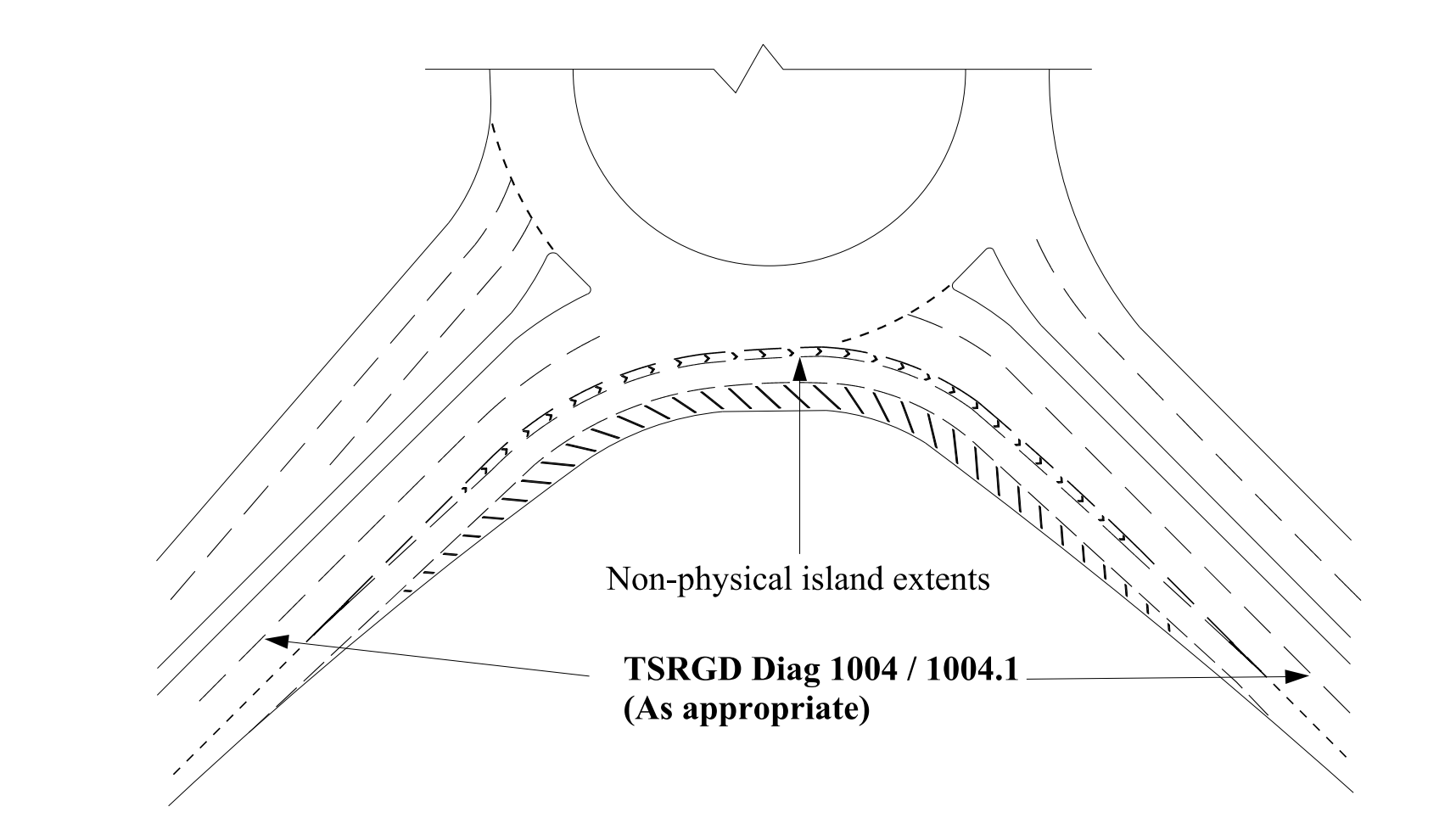
NOTE Further requirements and guidance on the use of lane markings is provided in UKSI 2016/362 (TSRGD) [Ref 9.N].
6.23 On the approach and exit to the non-physical island hatched road markings shall be provided.
Measuring stopping sight distance (SSD) on a segregated left turn lane
6.24 The desirable minimum SSD for the SLTL shall be the lesser of:
- the SSD obtained from CD 109 [Ref 4.N] for the design speed of the approach; or,
- the SSD given in Table 6.27 of this document appropriate to the maximum nearside curve radius.
6.25 The desirable minimum SSD for an SLTL shall be applied to the section of SLTL between the end of the entry taper and the start of exit taper.
6.26 The desirable minimum SSD on the SLTL up to the end of the entry taper and after the start of the exit taper shall be calculated in accordance with CD 109 [Ref 4.N].
NOTE Requirements and advice for the visibility on the approach to an SLTL are provided in CD 109 [Ref 4.N]. The SSD is measured from the centre of the approach or exit lane to the centre of the SLTL lane.
6.27 The maximum curve radius used to determine the SSD from Table 6.27, shall be the greater of either the entry or exit radius of the SLTL.
| Maximum nearside kerb radius (metres) | Desirable minimum SSD (metres) |
|---|---|
| ≤ 20 | 35 |
| > 20 - 40 | 70 |
| > 40 - 80 | 90 |
| > 80 - 100 | 120 |
| > 100 - 120 | 160 |
| > 120 | 215 |
NOTE 1 The entry or exit radius of the SLTL is the nearside kerb radius that occurs immediately after the entry taper and immediately before the exit taper in the direction of travel.
NOTE 2 See Figures 6.27N2a and 6.27N2b for details of entry and exit tapers and nearside kerb radii.
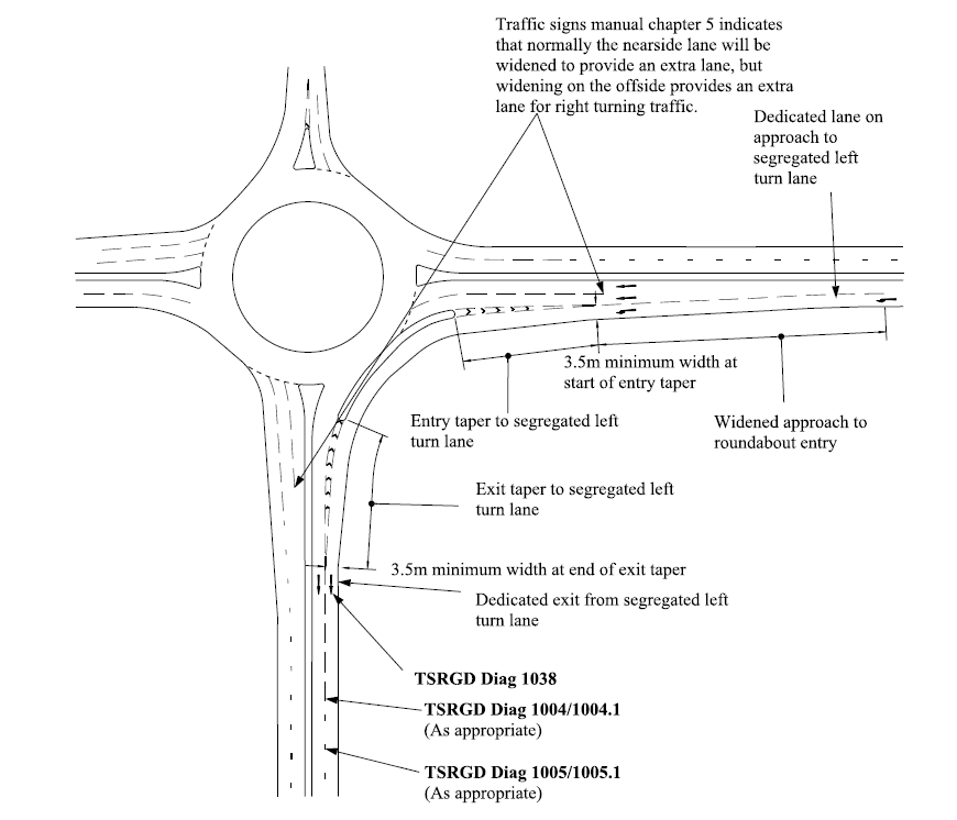
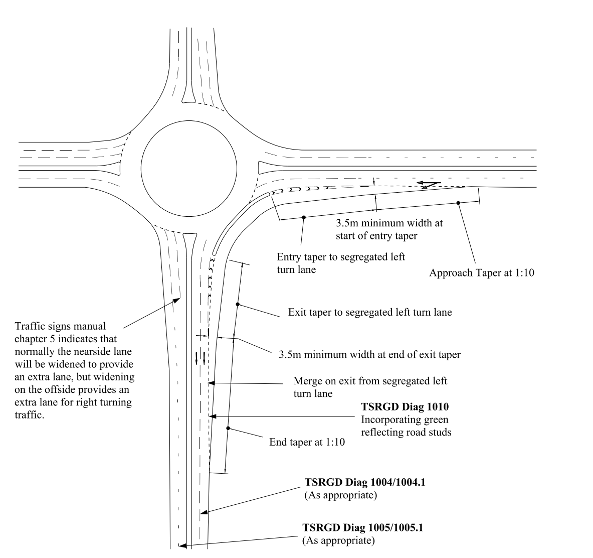
Segregated left turn lanes approach layout
6.28 SLTLs shall not be used at junctions where the approach road gradient is in excess of 4%.
6.28.1 The gradient of the approach should be measured back along the mainline from the start of the entry taper.
NOTE Further requirements and advice for the measurement of the gradient are provided in CD 109 [Ref 4.N].
6.29 The longitudinal gradient along the SLTL shall not exceed 4%.
6.30 The approach arrangement of SLTLs shall consist of either a dedicated lane (refer to Figure 6.27N2a) or a diverge on the approach arm (refer to Figure 6.27N2b).
6.31 Where a diverge is proposed, the entry arrangements shall consist of an approach taper, in accordance with Table 6.31, and as shown on Figure 6.27N2b and Figure 6.31.
| Approach type | Approach taper | Entry taper |
|---|---|---|
| Dedicated approach lane | No | Yes |
| Diverge | Yes | Yes |
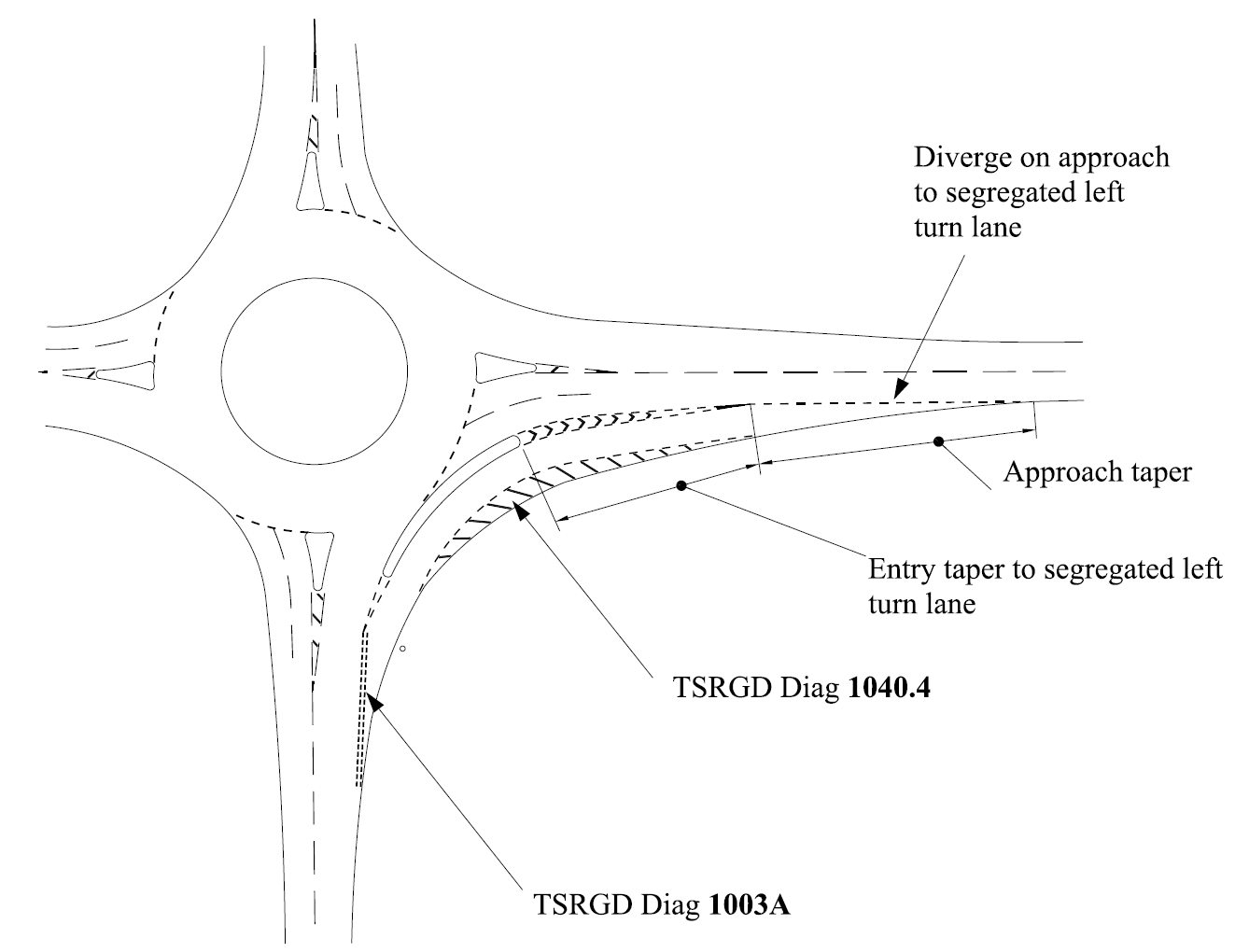
NOTE Further requirements and advice on road markings and signs are provided in UKSI 2016/362 (TSRGD) [Ref 9.N], TSM Chapter 3 [Ref 12.N], TSM Chapter 4 [Ref 13.N] and TSM Chapter 5 [Ref 14.N].
6.32 The approach taper is related to the design speed and minimum taper ratio values contained in Table 6.32 shall be applied.
| Design speed | Minimum taper ratio |
|---|---|
| ≤ 60 km/h | 1:10 |
| >60 km/h | 1:15 |
6.33 The entry taper length for the SLTL shall be provided in accordance with Table 6.33.
| Design speed (km/h) |
Entry/exit taper length factors |
|---|---|
| 50 | 20 |
| 60 | 20 |
| 70 | 20 |
| 85 | 25 |
| ≥100 | 30 |
NOTE The entry / exit taper length factors are utilised in calculating the entry / exit taper lengths as illustrated in Figure 6.37.1 below.
6.34 The SLTL width shall be a minimum of 3.5 metres at the start of the entry taper, as shown on Figure 6.27N2a.
6.35 Any widening required to accommodate the swept path of HGVs shall be developed along the length of the entry taper.
NOTE The length of the entry taper is dependent on the widening required to accommodate either the segregated left turn lane island width, or the widening required to accommodate the swept path of HGVs (see Table 6.33).
6.36 The length of the entry taper shall be subject to a minimum width of 1 metre for a non-physical island.
6.37 The length of the entry taper shall be subject to a minimum width of 2.2 metres (1.6 metre island width plus 0.3 metre marking offset on each side) for a physical island, except in the following circumstance:
- the 0.3 metre offset can be reduced to 0.15 metres where the speed limit is 40mph or less and there is limited width between the island and the nearside kerb.
NOTE Guidance on offset and markings is provided in TSM Chapter 5 [Ref 14.N].
6.37.1 The taper for the hatching should be developed asymmetrically on the SLTL side of the entry taper as shown on Figure 6.37.1.
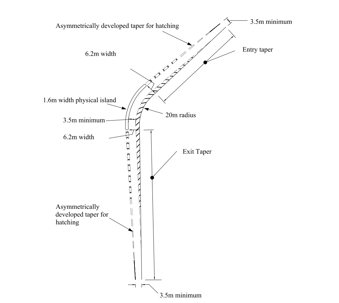
NOTE Example calculation of entry / exit taper length, based on requirements in Section 6:
- establish physical island width;
- establish widening required for physical island (physical island width plus offset to the outside edge of the marking);
- establish widening for HGV (lane width required at the physical island minus the lane width before the entry taper begins / after the exit taper ends;
- use whichever widening is greater in the taper calculation;
- use the speed of the approach road / exit road to establish the entry / exit taper length factor from Table 6.33;
- multiply the widening by the taper length factor to get the taper length.
| Physical island width (metres) | Widening for island (metres) | Widening for HGV (metres) | Widening to be used for taper calculation (metres) |
Speed of approach/exit road (km/h) | Taper length factor (from Table 6.33) |
Taper length (metres) | |
|---|---|---|---|---|---|---|---|
| Entry taper | 1.6 | 1.6 + (2 x 0.3) = 2.2 | 6.2 - 3.5 = 2.7 | 2.7 > 2.2 use 2.7 | 70 | 20 | 2.7 x 20 = 54 |
| Exit taper | 100 | 30 | 2.7 x 30 = 81 |
6.37.2 The taper for the hatching should terminate in a position offset 0.3 metres from the edge of a physical island as shown on Figure 6.37.2.
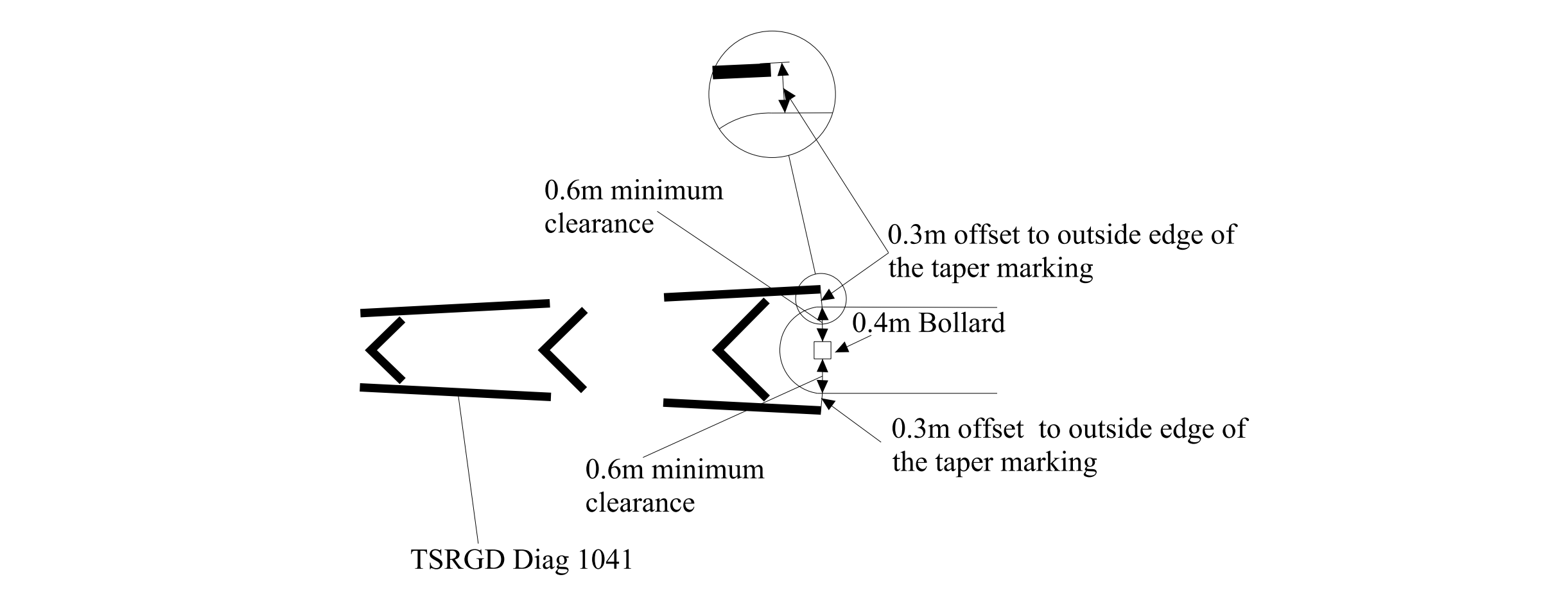
6.38 The larger of the two values (that is, the widening required to accommodate either the SLTL island width, or the widening required to accommodate the swept path of heavy goods vehicles (HGVs)) shall be used to calculate the entry taper length using the factors contained in Table 6.33.
Segregated left turn lanes exit layout
6.39 Where only one exit lane has been provided from the roundabout, a give way arrangement shall be provided from the SLTL (see Figure 6.39).
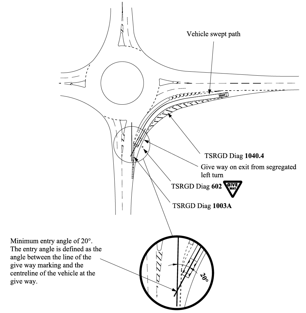
NOTE There are three basic types of SLTL exit layout:
- dedicated lane consisting of an exit taper as shown on Figure 6.27N2a;
- merge consisting of an exit and end taper as shown on Figure 6.27N2b;
- give-way as shown on Figure 6.39.
6.40 The exit taper for the SLTL shall be provided in accordance with Table 6.33.
6.40.1 As with the entry taper, the length of the exit taper should be calculated by using the larger value when comparing the width of the SLTL island with the lane width reduction required between the start and end of the exit taper, as shown on Figure 6.37.1.
6.40.2 The taper for the hatching should be developed asymmetrically on the SLTL side of the exit taper as shown on Figure 6.37.1.
6.40.3 The taper for the hatching should terminate in a position offset from the edge of a physical island in accordance with the method described for approach layouts in Section 6.
6.41 Any widening required to accommodate the swept paths of HGVs through the SLTL shall be removed along the length of the exit taper.
6.42 Where an SLTL is present, the exit width reduction shall be completed before the SLTL exit taper.
6.42.1 As a result of the reduction in exit width, the SLTL exit taper may be extended to accommodate the roundabout exit width reduction.
NOTE Further geometric requirements on roundabout exit layouts are provided in Section 3.
6.43 The SLTL width shall be a minimum of 3.5 metres at the end of the exit taper, as shown on Figure 6.27N2a.
6.44 The end taper is related to design speeds and the minimum taper values contained in Table 6.44 shall be provided.
| Design speed | Minimum taper |
|---|---|
| ≤ 60 km/h | 1:10 |
| > 60 km/h | 1:15 |
6.45 A give way exit from a SLTL shall be at a minimum entry angle of 20°.
6.45.1 An SLTL give way exit should be located close to the roundabout.
6.46 To calculate the entry angle from the SLTL on to the mainline, the position of the vehicle at the give way shall be determined by carrying out a swept path analysis.
NOTE The entry angle is defined as the angle between the line of the give way marking in accordance with UKSI 2016/362 (TSRGD) [Ref 9.N] diagram 1003A (Schedule 9 Part 6 Item 3) and the centre line of the vehicle at the give way as shown on Figure 6.39.
6.47 Where traffic signs and street furniture are placed on the physical island in the vicinity of the exit, they shall be located so as not to obstruct road user visibility between the SLTL exit and adjacent roundabout exit lane.
Road markings and signs for segregated left turn lanes
6.48 The presence of an SLTL shall be signed on the approach using advance direction signs (ADS).
NOTE Guidance on the design of the ADS route symbol is given in TSM Chapter 7 [Ref 16.N].
6.48.1 In the case of a lane drop layout, a left turn arrow should be placed in the lane at its commencement and repeated if necessary until the entry taper chevron marking commences in accordance with UKSI 2016/362 (TSRGD) [Ref 9.N] diagram 1038 (Schedule 11 Part 4 Item 20).
6.48.2 The use of road markings to supplement ADS should be provided in accordance with UKSI 2016/362 (TSRGD) [Ref 9.N] diagram 1035 (Schedule 11 Part 4 Item 19).
NOTE Single arrows are used in combination with destinations and/or route numbers.
6.48.3 Where an SLTL follows a tight horizontal radius relative to the approach speed or there are substandard vertical alignment features, “SLOW” road markings to UKSI 2016/362 (TSRGD) [Ref 9.N] diagram 1024 (Schedule 11 Part 4 Item 15) should be used in conjunction with associated warning signs to UKSI 2016/362 (TSRGD) [Ref 9.N] diagram 512 (Schedule 2 Part 2 Item 8) (Bend ahead), plated with either UKSI 2016/362 (TSRGD) [Ref 9.N] diagram 511 (Schedule 2 Part 3 Item 1) (REDUCE SPEED NOW) or diagram 513.2 (Schedule 2 Part 3 Item 2 and Schedule 13 Part 4 Item 2) (Max speed).
NOTE Further requirements and guidance on the use of supplementary plates is provided in UKSI 2016/362 (TSRGD) [Ref 9.N] and TSM Chapter 4 [Ref 13.N].
6.48.4 On an SLTL with a tight horizontal radius, if the superelevation provided does not meet the required standards set out in Sections 3 and 6 of this document, an appropriate supplementary plate should be provided with the sign to UKSI 2016/362 (TSRGD) [Ref 9.N] diagram 512 (Schedule 2 Part 2 Item 8).
6.48.5 Traffic signs should be located to avoid sign clutter or confusion to drivers not using the SLTL.
NOTE Traffic signs and street furniture placed on physical islands can create confusion, distract, reduce visibility, add to sign clutter and have maintenance and road safety implications.
6.48.6 When there is risk of confusion between the distance to the commencement of the SLTL and the distance to the roundabout give way line, count down signs in accordance with UKSI 2016/362 (TSRGD) [Ref 9.N] diagram 823 (Schedule 11 Part 2 Item 21), diagram 824 (Schedule 11 Part 2 Item 21) and diagram 825 (Schedule 11 Part 2 Item 21) should not be provided on a dual carriageway approach to a roundabout.
6.49 Where a physical island is to be provided, a plain faced lit bollard shall be installed at the start of the island facing oncoming traffic.
6.50 A minimum clearance of 0.6 metres between the edge of any sign or bollard and edge of the physical island shall be provided.
6.50.1 Where the conspicuousness of the physical island requires enhancement, the surface of the island may be finished in a colour that contrasts with the surfacing of the adjacent running carriageway.
NOTE 1 Where the conspicuousness of the approaches to a physical SLTL islands requires enhancing, coloured surfacing under the UKSI 2016/362 (TSRGD) [Ref 9.N] diagram 1041 (Schedule 11 Part 4 Item 27) entry taper road markings can be used.
NOTE 2 The UKSI 2016/362 (TSRGD) [Ref 9.N] diagram 1041 (Schedule 11 Part 4 Item 27) entry taper road markings can be enhanced by using specialist profiled and reflectorised materials to make them more conspicuous during the hours of darkness or during inclement weather.
6.50.2 On a physical island SLTL, hard surfaces should be provided.
NOTE Hard surfaces are recommended for ease of maintenance and to avoid obstruction of visibility.
6.51 Where pedestrian, cyclist and / or equestrian facilities are provided on an SLTL, warning signs indicating the presence of the facilities shall be used.
NOTE Guidance on the provision of warning signs is given in TSM Chapter 4 [Ref 13.N].
6.52 Where there are road markings for the SLTL that are not to be crossed, red reflecting road studs shall be used.
NOTE 1 Red reflecting road studs can be used with:
- advisory markings ( UKSI 2016/362 (TSRGD) [Ref 9.N] diagram 1040.4 (Schedule 11 Part 4 Item 25) and diagram 1041 (Schedule 11 Part 4 Item 27)); or
- regulatory markings ( UKSI 2016/362 (TSRGD) [Ref 9.N] diagram 1042 (Schedule 9 Part 6 Item 22)).
NOTE 2 Guidance on the use of reflecting road studs is contained in TSM Chapter 5 [Ref 14.N].
6.53 Any hatching to narrow down the lane width on the nearside shall be in accordance with UKSI 2016/362 (TSRGD) [Ref 9.N] diagram 1040.4 (Schedule 11 Part 4 Item 25), as shown in Figures 6.53.2a and 6.53.2b.
6.53.1 Where a SLTL has been widened to accommodate the swept paths of HGVs, measures should be incorporated to discourage high vehicle speeds or two vehicles attempting to use the lane side by side as result of the increased carriageway width.
6.53.2 Hatching to UKSI 2016/362 (TSRGD) [Ref 9.N] diagram 1040.4 (Schedule 11 Part 4 Item 25) should be a minimum width of 1.0 metre (see Figures 6.53.2a and 6.53.2b).

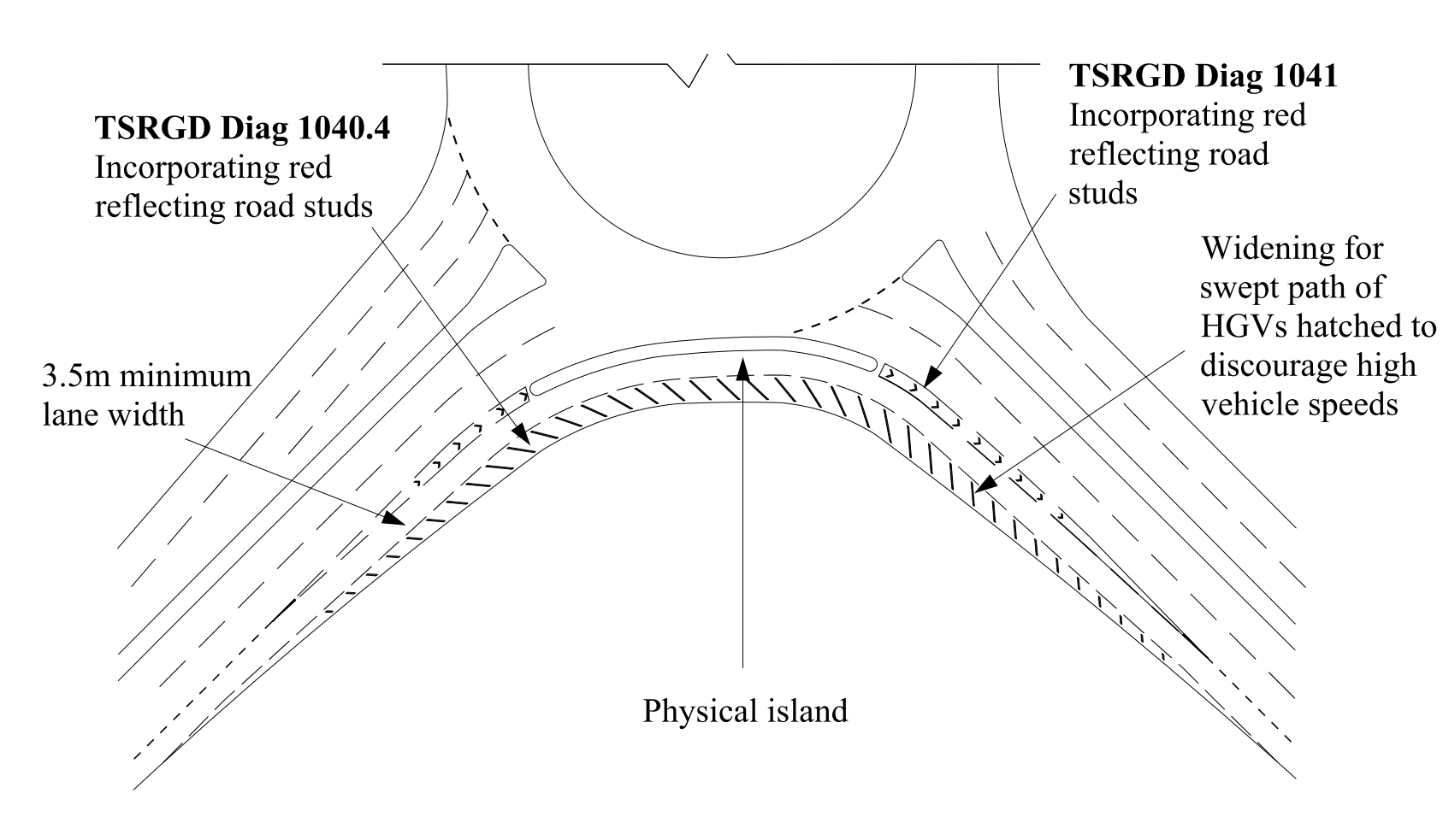
7. Design of subsidiary deflection islands
Criteria for subsidiary deflection islands
7.1 A subsidiary deflection island (SDI) shall not be used in the design of new normal or compact roundabouts.
NOTE Additional requirements and advice for the geometric design of all roundabouts are provided in Section 3.
7.1.1 SDIs may be incorporated into the design of an improvement scheme to existing roundabouts to address sub-standard entry path curvature.
NOTE Appendix C provides a decision process for the inclusion of an SDI.
7.2 SDIs shall only be incorporated into the design where the required deflection on an existing roundabout, as defined and measured according to this document cannot be achieved through conventional design measures.
NOTE 1 Examples of traffic deflection islands, and physical and non-physical SDIs are illustrated in Figure 7.2N1.
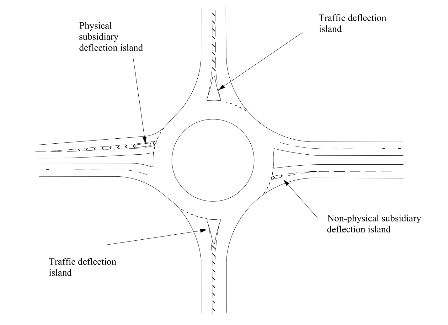
NOTE 2 In urban areas the restrictions on space available, coupled with the turning width requirements of HGVs, can result in normal roundabouts that do not provide sufficient entry deflection to the left by means of the central island alone.
NOTE 3 In cases where adequate deflection is not achieved, deflection can be generated by means of enlarged traffic deflection islands (Figure 7.2N3a) or, if these cannot be provided at existing roundabouts, by non-physical SDIs in the entry as shown on Figure 7.2N3b.
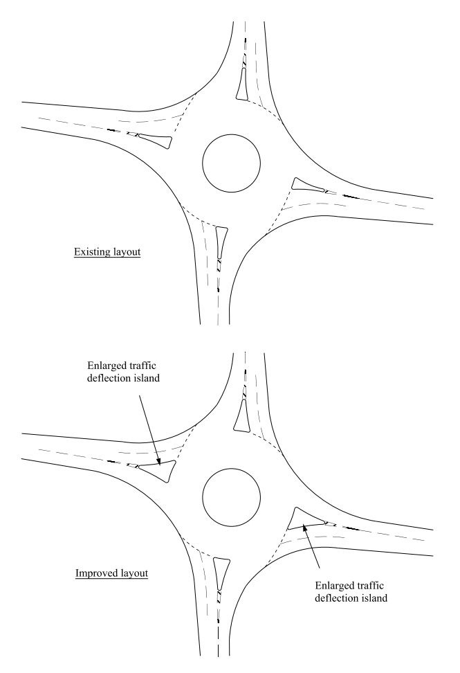
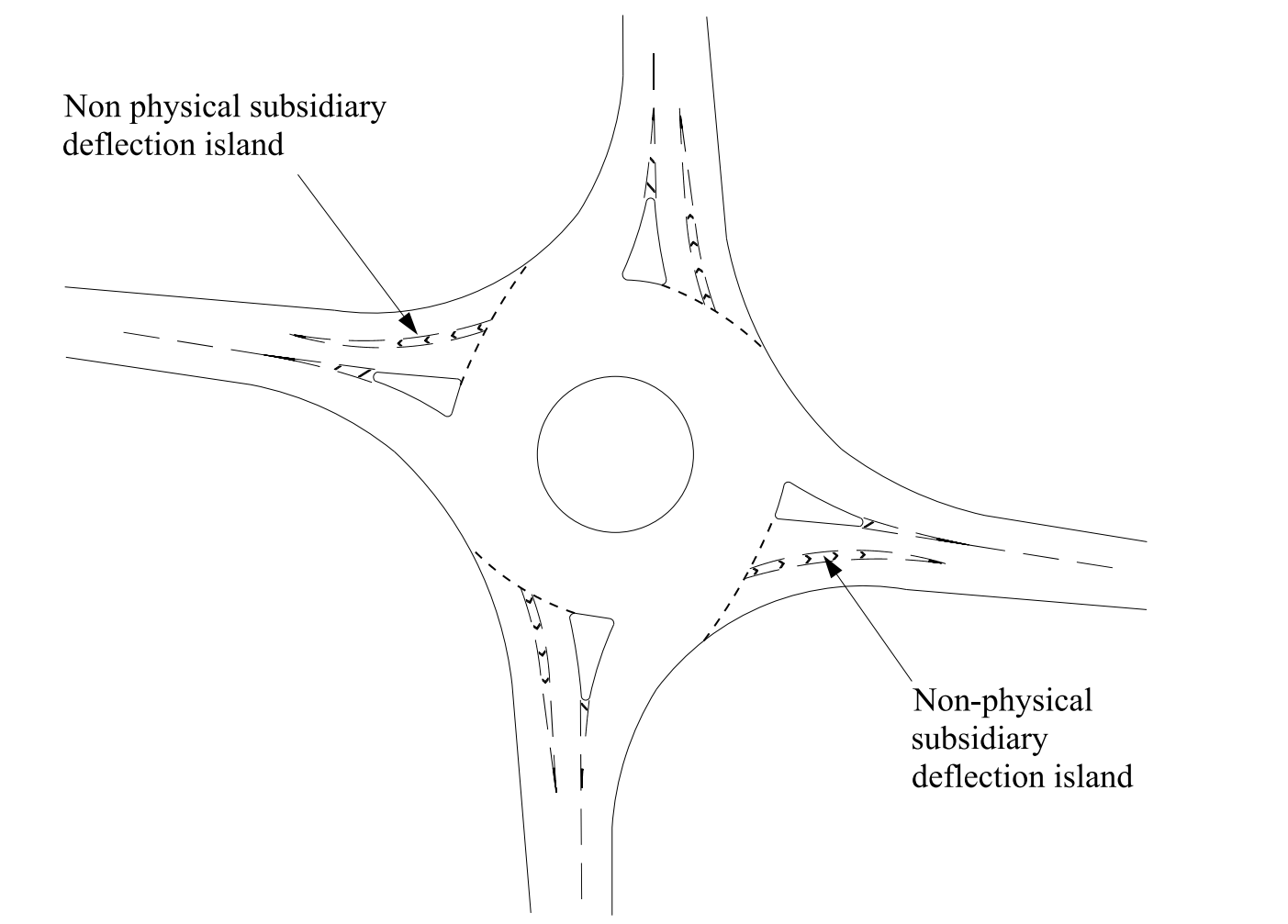
7.2.1 Non-physical SDIs should only be used where the option for a physical SDI has been discounted for reasons of available space or safety.
NOTE Non-physical SDIs are subject to abuse by drivers crossing the hatched road markings and therefore are less effective than physical islands.
7.3 Non-physical SDIs shall not be used on sections of highway / road where pedestrians, cycle traffic and equestrians are known to cross.
NOTE Advice on provisions for pedestrians, cyclists and equestrians is given in Section 8 of this document.
7.4 Physical SDIs shall only be used at street lit junctions.
7.5 Where the SDI is situated on an abnormal load route, the use of a physical SDI shall be assessed to demonstrate sufficient swept path width is provided for the abnormal load vehicle anticipated to use the SDI.
7.5.1 Where sufficient carriageway width cannot be provided between kerbs, a non-physical SDI island should be assessed for implementation providing that other conditions laid down in Figure C.2 and requirements elsewhere in this document are met.
Geometry requirements for subsidiary deflection islands
7.6 Physical SDIs shall be a minimum width of 1.6 metres.
NOTE The width of a physical SDI is subject to the provisions for pedestrians, cycle traffic and equestrians.
7.7 Non-physical SDIs shall be a minimum width of 1 metres.
7.8 Physical SDIs shall be offset a minimum of 2.4 metres from the roundabout give-way line to avoid the lit bollard obstructing visibility.
7.9 The island shall be a minimum total length of 5 metres.
NOTE Examples showing the minimum island length for generic physical and non-physical SDI for a 60 km/h approach design speed are shown on Figures 7.9Na and 7.9Nb. The approach hatching taper requirement is indicated in Table 7.15 below.
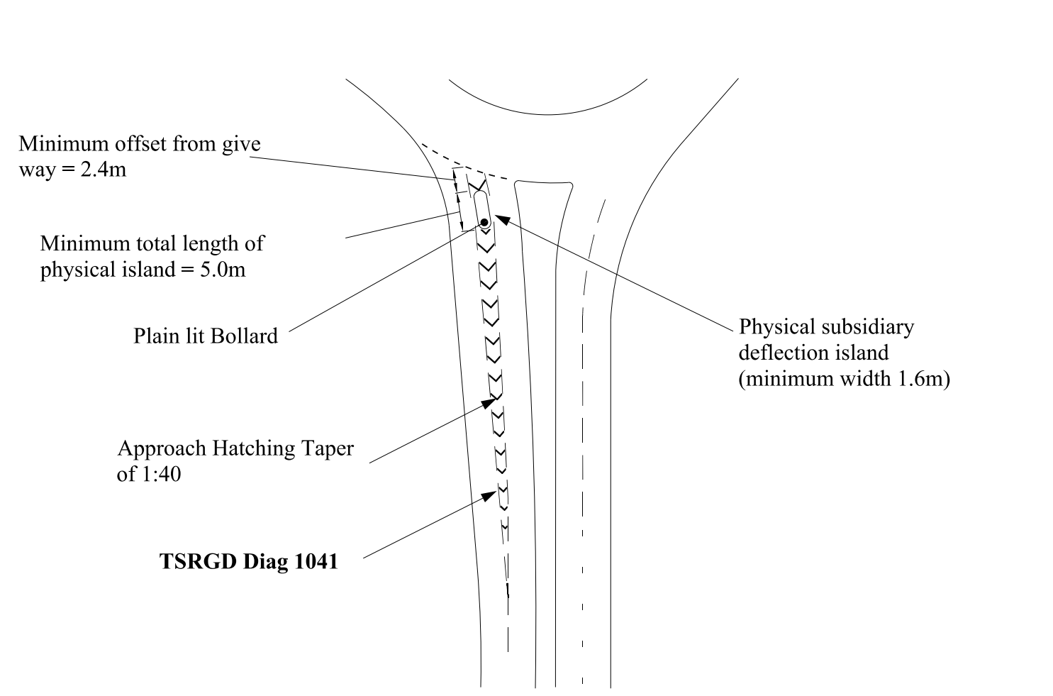
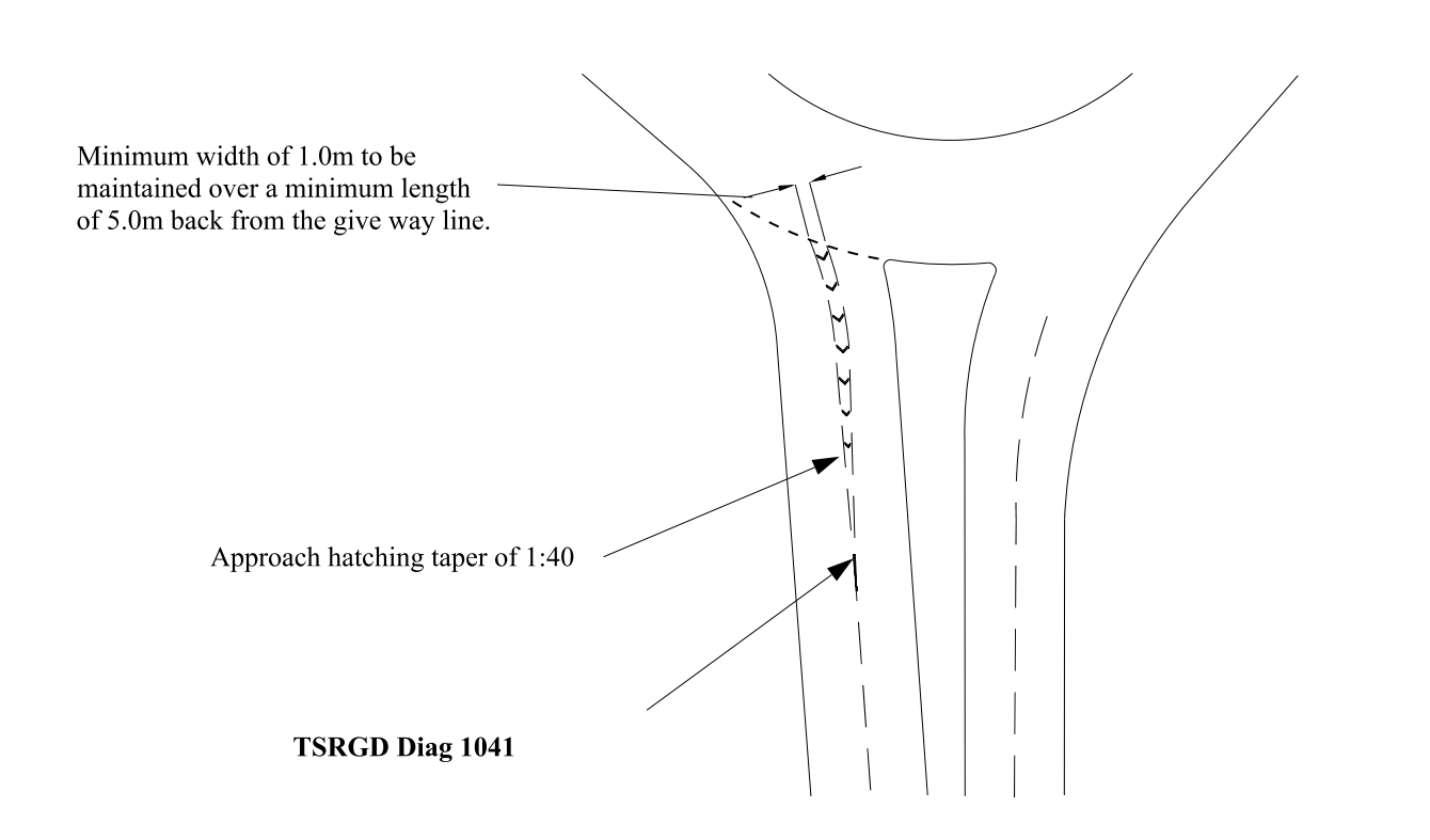
7.10 Where an SDI is provided, the entry path curvature shall be measured in accordance with the guidance contained in Section 3 of this document and as shown on Figure 7.10.
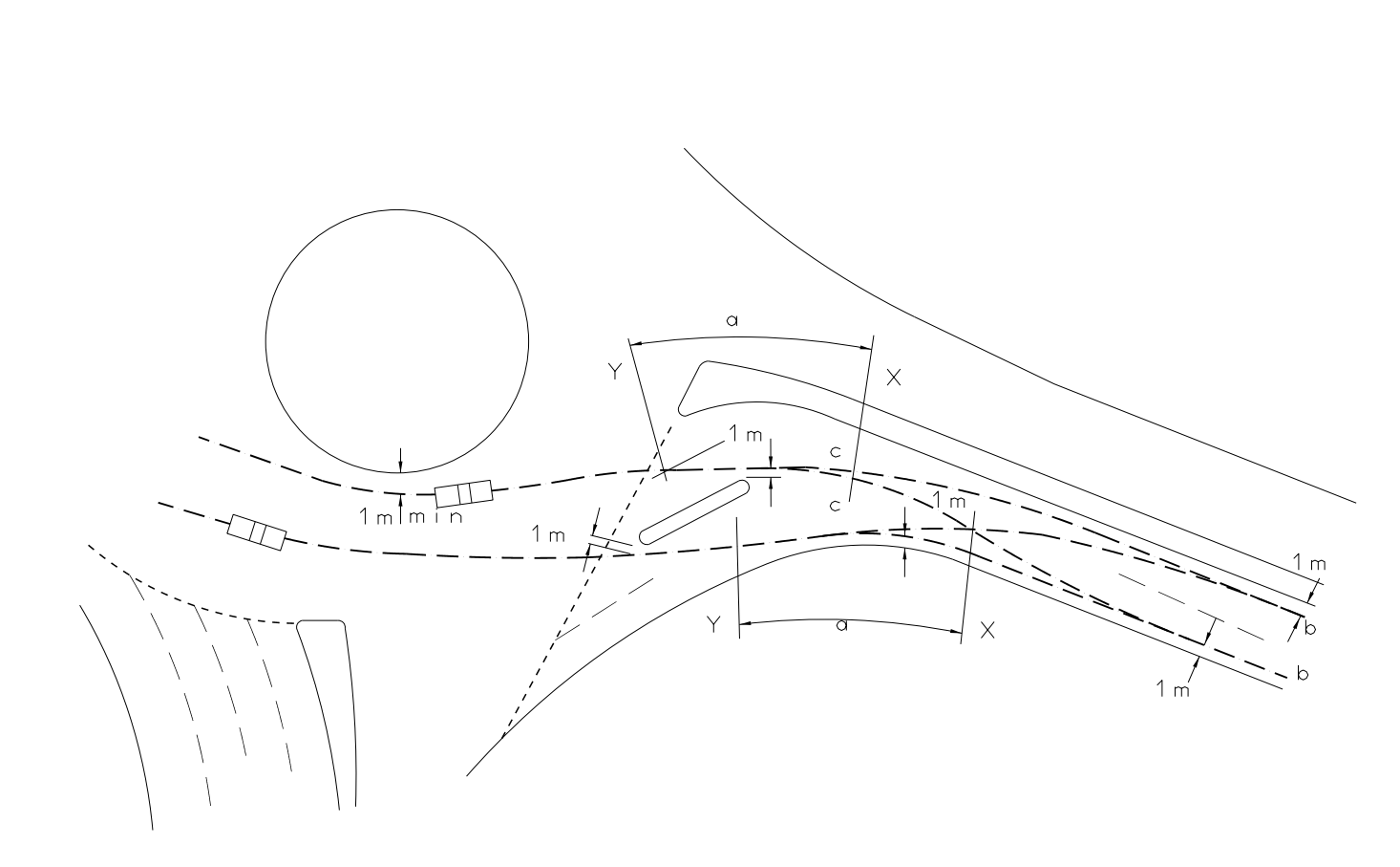
NOTE 1 Figure 7.10 is for illustration purposes only and is intended to show the method of constructing entry path curvature where SDIs are present.
NOTE 2 In Figure 7.10, 'c' represents the vehicle entry path.
7.10.1 The radius, a (indicated on Figure 7.10), should be measured over a distance of 20 to 25 metres.
NOTE It is the smallest radius that occurs along the approach entry path in the vicinity of the give way line but not more than 50 metres in advance of the give way line.
7.10.2 The commencement point, b, of the entry path curvature should be at a point not less than 50 metres from the give way line:
- either 1 metre from nearside kerb; or,
- 1 metre from offside kerb for dual two-lane carriageway; or,
- 1 metre from nearside kerb; or,
- 1 m from centre line for single two-lane carriageway.
7.11 Where a physical SDI is proposed and cycle traffic is anticipated on a road, a minimum carriageway width of 4.5 metres shall be maintained between carriageway edge kerbs or any carriageway edge road markings.
Road markings for subsidiary deflection islands
7.12 Road markings on non-physical SDIs shall not be raised.
NOTE Non-physical SDIs are areas defined by road markings and road studs only.
7.13 Areas of solid marking material shall not be used (with the exception of coloured surfacing used under areas of hatching).
NOTE Where road safety concerns have been identified in respect of visibility to the SDI, the conspicuousness of the SDI can be enhanced through the use of coloured surfacing within the area of hatched road markings.
7.14 Road markings to UKSI 2016/362 (TSRGD) [Ref 9.N] diagram 1041 (Schedule 11 Part 4 Item 27) shall be used to guide vehicles past the physical island, as shown in Figure 7.9Na.
7.15 The approach hatching for both physical and non-physical SDIs shall be in accordance with Table 7.15.
| Design speed (km/h) | Approach hatching taper |
|---|---|
| 50 | 1:40 |
| 60 | 1:40 |
| 70 | 1:45 |
| 85 | 1:45 |
| ≥100 | 1:50 |
7.16 The approach hatching for SDIs shall be developed symmetrically.
7.16.1 The approach hatching for SDIs should terminate at a position offset from each side of a physical SDI.
NOTE Guidance on the provision of approach hatching is provided in TSM Chapter 5 [Ref 14.N].
7.17 The approach hatching for physical SDIs to UKSI 2016/362 (TSRGD) [Ref 9.N] diagram 1041 (Schedule 11 Part 4 Item 27) shall continue at full width from the end of the island up to the roundabout give way.
7.18 Where a physical SDI is to be provided, a plain faced lit bollard shall be installed at the start of the island.
7.18.1 A minimum clearance of 0.6 metres should be provided between the edge of any sign or bollard and the edge of kerb of a physical SDI.
7.18.2 On a physical SDI, hard surfaces should be provided for ease of maintenance and to avoid possible obstruction of visibility.
NOTE Hard surfaces are recommended for ease of maintenance and to avoid obstruction of visibility.
7.19 Red reflecting road studs shall be used in conjunction with road markings to UKSI 2016/362 (TSRGD) [Ref 9.N] diagram 1041 (Schedule 11 Part 4 Item 27) along the chevron marking, on both sides of the marking.
NOTE Guidance on the use of reflecting road studs is contained in TSM Chapter 5 [Ref 14.N].
8. Designing for pedestrians, cyclists and equestrians at roundabouts
General
8.1 Where there is demand or the desire to encourage pedestrians, cyclists, and / or equestrians at roundabouts, these users shall be provided for.
NOTE 1 Demand for pedestrians, cyclists and equestrians can be catered for off network where it is not suitable to provide facilities on or adjacent to the highway / road.
NOTE 2 Requirements and advice on the provision of cycle traffic facilities on trunk roads are given in CD 195 [Ref 3.I]. Design guidance for cycle traffic facilities on the local road network can be obtained from the local authority.
NOTE 3 Requirements and advice on the provisions for pedestrians, equestrians and shared use facilities are given in CD 143 [Ref 2.N].
NOTE 4 Additional requirements and advice for the design of pedestrian and cycling facilities at roundabouts are provided in the National Application Annexes.
NOTE 5 Additional requirements for visibility at crossings are provided in Section 3, "Pedestrian crossing visibility".
NOTE 6 Guidance on inclusive mobility aspects is provided in Inclusive Mobility [Ref 6.I].
NOTE 7 Guidance on tactile surfaces is provided in TSM Chapter 6 [Ref 15.N]and GUTPS [Ref 4.I].
8.1.1 Where the speed limit within 100 metres of the give way line is greater than 40mph on any approach, and the traffic flow on any approach is greater than 8,000 two-way AADT, any pedestrian crossing facilities provided should be either signal-controlled or grade-separated.
8.1.2 Where the roundabout is situated on a single carriageway with a speed limit greater than 40mph and the traffic flow on each of the approaches is less than 8,000 two-way AADT, crossing facilities may be uncontrolled crossings.
8.1.3 Where the speed limit within 100 metres of the give way line on all approaches is less than or equal to 40mph, Table 8.1.3 below provides suggestions on what crossing facilities may be provided for pedestrians.
| Highest class of road on any approach | Highest two-way AADT on any approach | Suggested pedestrian crossing provision |
|---|---|---|
| Single | < 8000 | Uncontrolled |
| 8000 - 12000 | Uncontrolled / Zebra | |
| > 12000 | Zebra | |
| Dual | < 16000 | Uncontrolled / Zebra |
| 16000 - 25000 | Zebra / Signal-controlled | |
| > 25000 | Signal-controlled |
NOTE In TSM Chapter 6 [Ref 15.N], zebra crossings are not recommended to be installed on roads with an 85th percentile speed of 35mph or above. This publication also provides additional guidance on choice of crossing provision.
8.1.4 To keep crossings short, stand-alone pedestrian crossing facilities should be outside the flared section, on normal and compact roundabouts without the provision of SLTLs or SDIs, as shown in Figure 8.1.4.
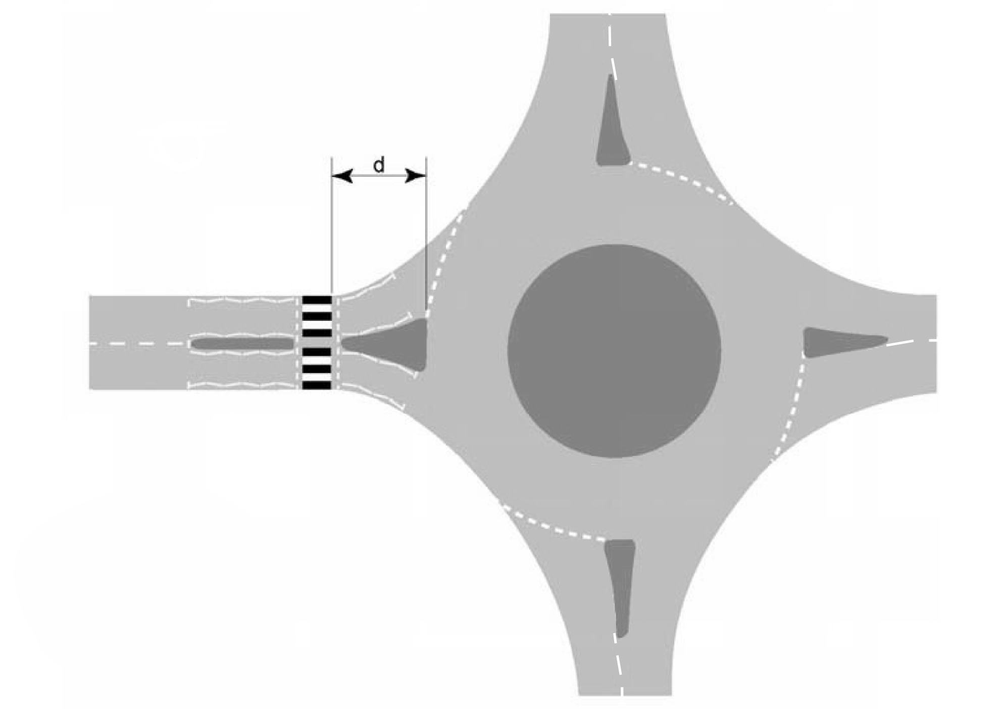
NOTE The distance 'd' shown in Figure 8.1.4 is the entry flare length.
Controlled crossings
8.2 Zigzag markings shall not be used where the crossing is part of a signal-controlled roundabout.
8.2.1 Where a signal-controlled crossing is used, the signals should be positioned to reduce the risk of drivers confusing the green signal with one controlling flow into the roundabout.
NOTE The provision of traffic signals on entries to the roundabout assist in separating the conflict between vehicular and pedestrian movements.
8.2.2 Where a signal-controlled crossing is located close to the give way line and drivers could confuse the crossing with the roundabout entry, the give way line should be supplemented by the use of markings to UKSI 2016/362 (TSRGD) [Ref 9.N] diagram 1023A (Schedule 9 Part 6 Item 4) and give way signs to diagram 602 (Schedule 9 Part 2 Item 2).
8.2.3 When signal-controlled pedestrian crossing facilities are incorporated on the exit arms on signal-controlled and non-signal-controlled roundabouts, storage length should be provided to avoid traffic queuing back onto the circulatory carriageway.
8.2.4 Non-staggered signal-controlled crossings should be sited either at 20 metres or more than 60 metres from the roundabout entry give way line.
NOTE 1 On the approach to the roundabout, a distance of 20 metres for a signal-controlled crossing can reduce the likelihood of drivers confusing the signal with one controlling flow into the roundabout and it leaves sufficient storage space for vehicles waiting to enter the roundabout.
NOTE 2 On the exit, a distance of 20 metres reduces the likelihood that ‘blocking back’ can occur where traffic queues extend onto the circulatory carriageway and it helps to ensure that drivers are still travelling slowly as they approach the crossing.
NOTE 3 Where the crossing is staggered, the part of the crossing on the entry arm can be within the 20 metres to 60 metres zone.
NOTE 4 The traffic island (extended as necessary) can be used as a central refuge.
NOTE 5 The central refuge can be used to form a staggered crossing.
NOTE 6 Where a near-side pedestrian crossing is used, both a staggered and non-staggered crossing can be considered. A stagger can be avoided where the driver is held at a red signal while the pedestrian is crossing.
Uncontrolled crossings at roundabouts
8.3 Kerbed islands provided to assist pedestrians crossing the roundabout shall be located within 20 metres of the give way line at the nearest point.
NOTE Uncontrolled crossings located more than 20 metres from the junction can be too far from the desire line, resulting in pedestrians not using the facility.
Specific advice for crossings on segregated left turn lanes (SLTL) and subsidiary deflection islands (SDI)
Pedestrian crossings on SLTL/SDI
8.4 On an SLTL, where a pedestrian refuge or physical SLTL is provided, it shall be a minimum width of 2 metres.
8.5 On an SLTL, where a pedestrian refuge or physical SLTL is provided, the hatching shall be a minimum width of 2.6 metres (or 2.3 metres where the speed limit is 40mph or less) adjacent to the refuge to allow for the offset, as illustrated in Figure 6.37.2.
NOTE Guidance on the interface of the hatching and island are provided in TSM Chapter 5 [Ref 14.N].
8.6 Where pedestrians are expected to cross an SLTL, controlled crossings or grade separated facilities shall be provided.
8.7 On a junction where either an SLTL or an SDI is present, a combination of both controlled and uncontrolled facilities shall not be used on the same arm of a junction.
8.7.1 Where a controlled crossing is used on the SLTL or SDI, other crossing facilities across the whole junction should be consistent.
NOTE Further requirements and guidance on provision of crossings on SLTLs and SDIs are provided in Sections 6 and 7.
8.8 SDIs shall be physical islands where they are intended to be used by pedestrians.
8.8.1 Where SDIs are intended to be used by pedestrians, measures should be incorporated into the design to direct pedestrians to use them as crossing points.
8.8.2 Where the islands are not intended for pedestrian use, measures should be incorporated into the design to discourage pedestrians from using them and instead to direct pedestrians to the designated crossing points.
NOTE SDIs can appear to create refuges that encourage pedestrians to cross at the location of the islands even if the islands are not intended as a pedestrian facility.
Cycle crossings on SLTL/SDI
8.9 When designing for cycle traffic at new SLTLs, cycle tracks shall be provided.
NOTE 1 Cycle tracks are provided to minimise road safety related risks at the start and end of the SLTL.
NOTE 2 Requirements and advice on provisions for cycle tracks are given in CD 195 [Ref 3.I].
NOTE 3 Both dedicated lanes and merge/diverge arrangements on approach and exit can create difficulties for cycle traffic.
NOTE 4 Requirements and guidance on signing to both instruct cycle traffic and warn approaching motorists regarding cycle tracks at SLTLs is provided in UKSI 2016/362 (TSRGD) [Ref 9.N] and TSM Chapter 4 [Ref 13.N].
8.10 Where cycle traffic is expected to cross physical SLTL islands (as shown on Figure 8.10), or a physical SDI, a minimum refuge island width of 3.0 metres shall be provided.
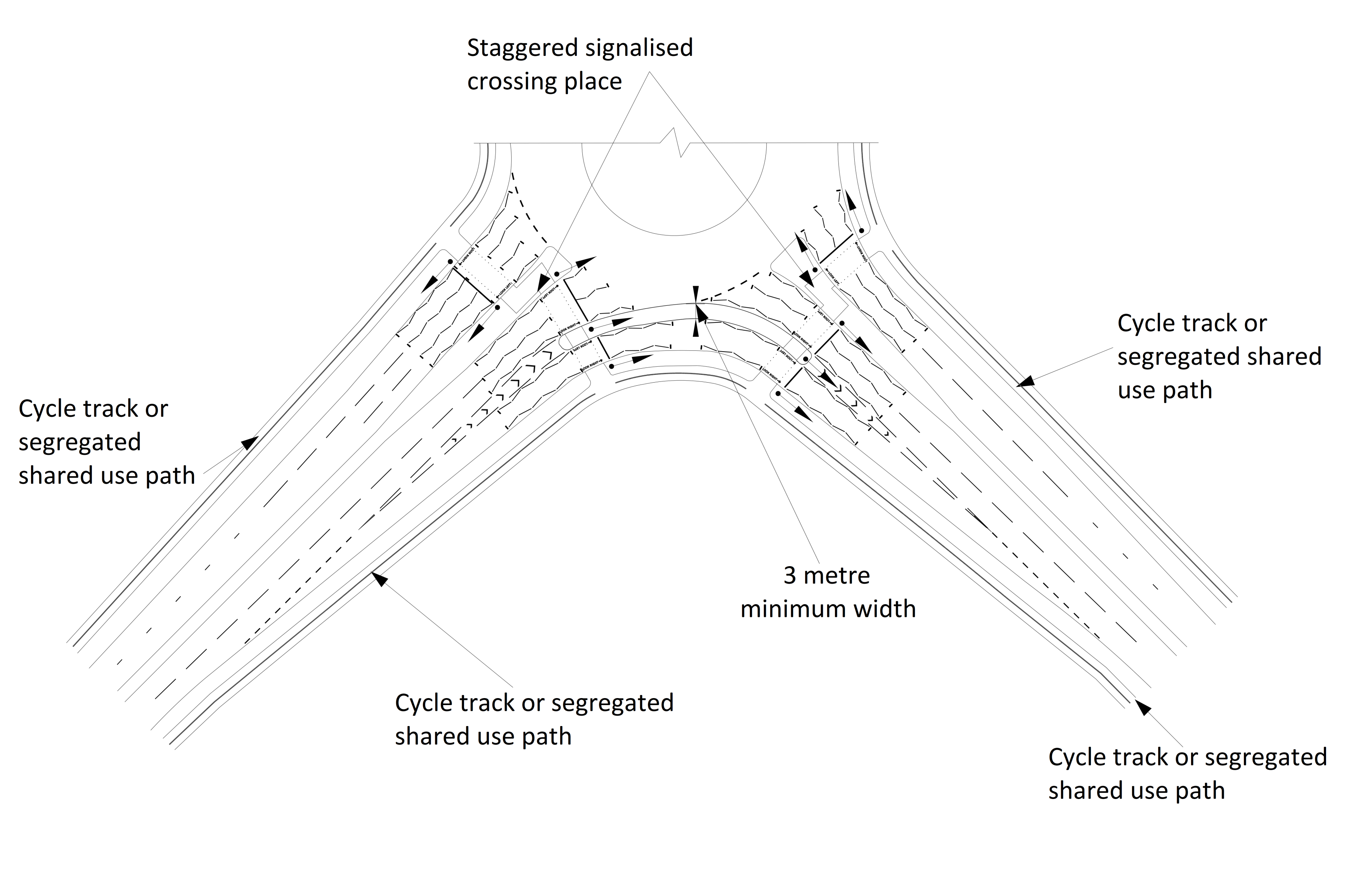
8.10.1 For all types of segregated lane, if it runs independently to the other approach lanes, then the crossing on the segregated lane island should be staggered.
8.11 Staggered crossings shall be designed so that central refuge island can accommodate the design parameters for the cycle design vehicle and two-way cycle track.
NOTE 1 Where appropriate, pedestrian and equestrian facilities can be incorporated in a staggered crossing.
NOTE 2 Additional examples of cycle track layout and signage on an SLTL are illustrated in Figures 8.11N2a and 8.11N2b. The requirements and advice for the SLTL crossing facilities are provided in Section 6.
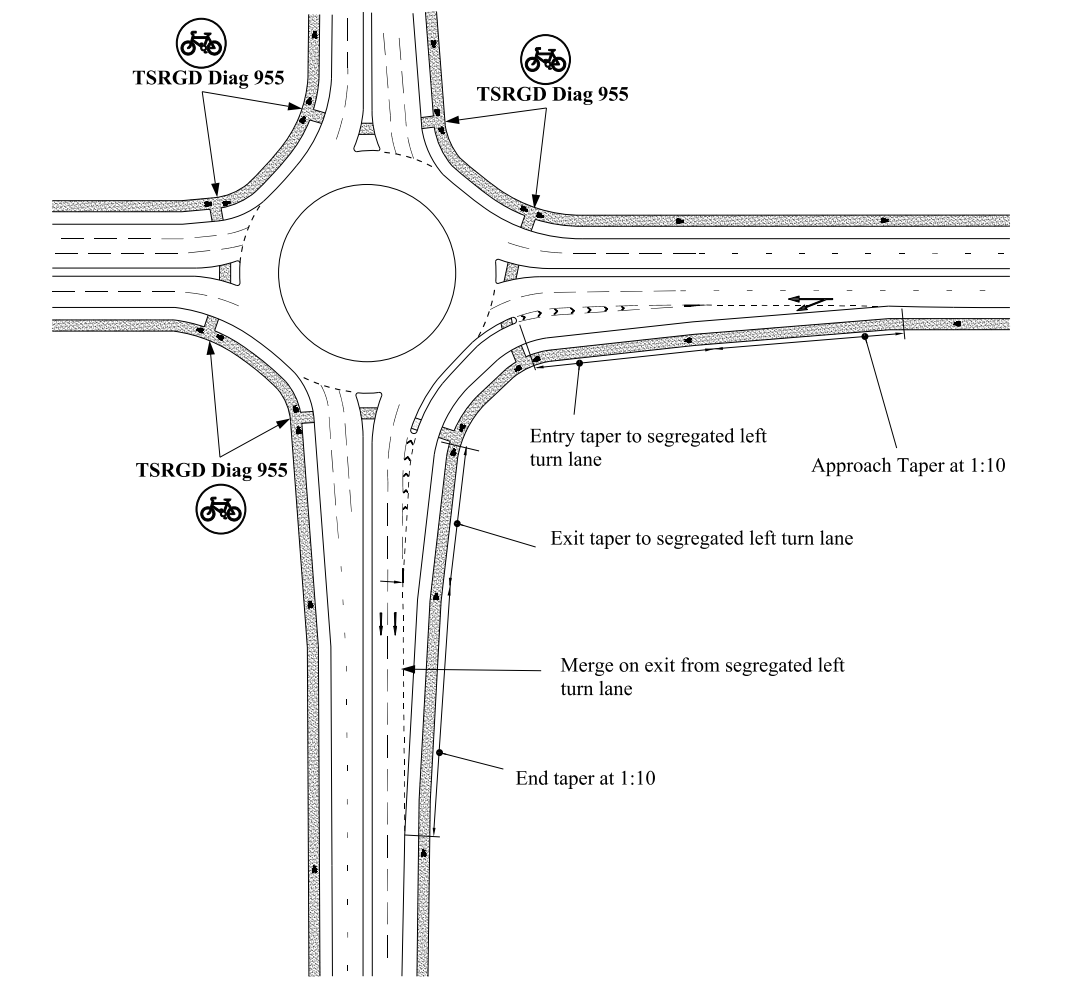
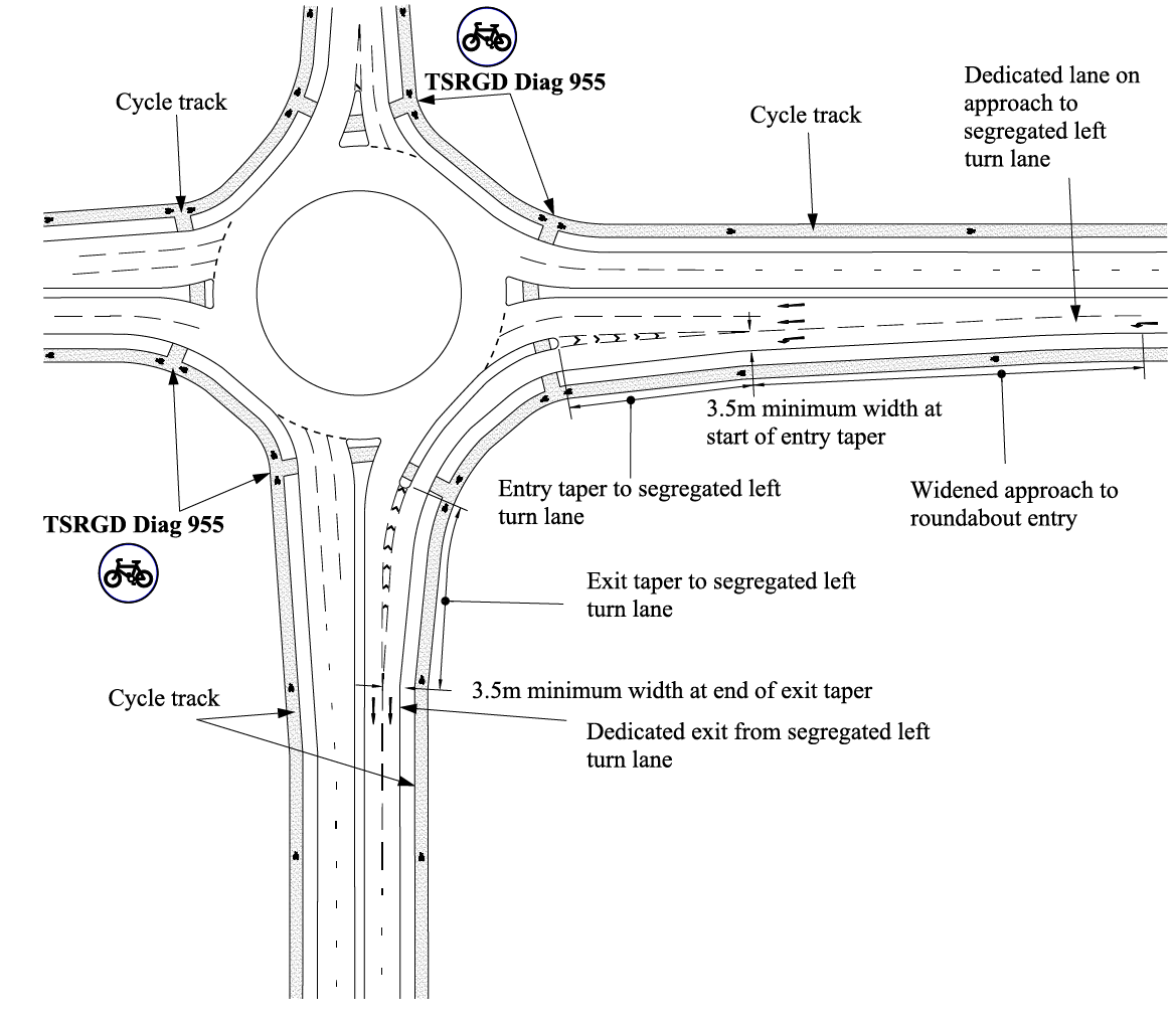
9. Normative references
The following documents, in whole or in part, are normative references for this document and are indispensable for its application. For dated references, only the edition cited applies. For undated references, the latest edition of the referenced document (including any amendments) applies.
| Ref. | Document |
|---|---|
| Ref 1.N | National Highways. CD 127, 'Cross-sections and headrooms' |
| Ref 2.N | National Highways. CD 143, 'Designing for walking, cycling and horse riding' |
| Ref 3.N | National Highways. CD 123, 'Geometric design of at-grade priority and signal-controlled junctions' |
| Ref 4.N | National Highways. CD 109, 'Highway link design' |
| Ref 5.N | National Highways. GG 101, 'Introduction to the Design Manual for Roads and Bridges' |
| Ref 6.N | National Highways. CD 146, 'Positioning of signalling and advance direction signs' |
| Ref 7.N | National Highways. CD 236, 'Surface course materials for construction' |
| Ref 8.N | National Archive. UKSI 1999/1026, 'The Highways (Traffic Calming) Regulations' |
| Ref 9.N | National Archive. UKSI 2016/362 (TSRGD), 'The Traffic Signs Regulations and General Directions' |
| Ref 10.N | Department for Transport. TAL 12/93, 'Traffic Advisory Leaflet 12/93 - Overrun Areas' |
| Ref 11.N | TSO. TSM Chapter 1, 'Traffic Signs Manual Chapter 1 - Introduction' |
| Ref 12.N | TSO. TSM Chapter 3, 'Traffic Signs Manual Chapter 3 - Regulatory Signs' |
| Ref 13.N | TSO. TSM Chapter 4, 'Traffic Signs Manual Chapter 4 - Warning Signs' |
| Ref 14.N | TSO. TSM Chapter 5, 'Traffic Signs Manual Chapter 5 - Road Markings' |
| Ref 15.N | TSO. TSM Chapter 6, 'Traffic Signs Manual Chapter 6 - Traffic Control' |
| Ref 16.N | TSO. TSM Chapter 7, 'Traffic Signs Manual Chapter 7 - The Design of Traffic Signs' |
10. Informative references
The following documents are informative references for this document and provide supporting information.
| Ref. | Document |
|---|---|
| Ref 1.I | Transport Research Laboratory. Kemp, R. N., Chinn, B. P. and Brock, G.. TRL LR 788, 'Articulated Vehicle Roll Stability - Methods of Assessments and Effects of Vehicle Characteristics' |
| Ref 2.I | Transport Research Laboratory. Kennedy, J. TRL PPR 206, 'Comparison of roundabout design guidelines' |
| Ref 3.I | National Highways. CD 195, 'Designing for cycle traffic' |
| Ref 4.I | https://www.gov.uk/government/publications/inclusive-mobility-using-tactile-paving-surfaces. Department for Transport. GUTPS, 'Guidance on the Use of Tactile Paving Surfaces' |
| Ref 5.I | Institute of Highway Engineers. IHE GfM, 'IHE Guidelines for motorcycling' |
| Ref 6.I | Department for Transport. https://www.gov.uk/government/publications/inclusive-mobility-making-transport-accessible-for-passengers-and-pedestrians. Inclusive Mobility, 'Inclusive mobility - A guide to best practice on access to pedestrian and transport infrastructure' |
| Ref 7.I | Transport Research Laboratory. G L Burtenshaw . TRL AG 72, 'Junctions 9 - User Guide' |
| Ref 8.I | National Highways. LD 117, 'Landscape design' |
| Ref 9.I | TSO. LTN 1/07, 'Local Transport Note 1/07 - Traffic calming' |
| Ref 10.I | TSO. LTN 1/09, 'Local Transport Note 1/09 - Signal controlled roundabouts' |
| Ref 11.I | Department for Transport. DfT Circular 01/13 , 'Setting local speed limits' |
| Ref 12.I | Transport Research Laboratory. Marie C Semmens. TRL RR 142, 'The Capacity of Entries to Very Large Roundabouts' |
| Ref 13.I | Transport Research Laboratory. Marie C Semmens. TRL SR 721, 'The Capacity of Some Grade-Separated Roundabout Entries' |
| Ref 14.I | National Archive. UKSI 1999/1025, 'The Highways (Road Humps) Regulations' |
| Ref 15.I | Transport Research Laboratory. TRL LR 942, 'The Traffic Capacity of Roundabouts ' |
| Ref 16.I | The Journal of the Institution of Highway Engineers . R. Stockdale. Stockdale Method, 'The Vertical Alignment Design of Roundabouts' |
| Ref 17.I | Department for Transport. TAL 2/05, 'Traffic Advisory Leaflet 2/05 - Traffic Calming Bibliography' |
| Ref 18.I | Department for Transport. TAL 7/95, 'Traffic Advisory Leaflet 7/95: Traffic Islands for Speed Control' |
| Ref 19.I | National Highways. CA 185, 'Vehicle speed measurement' |
| Ref 20.I | National Highways. GG 142, 'Walking, cycling and horse-riding assessment and review' |
| Ref 21.I | Transport Research Laboratory. R D Helliar-Symons. TRL LR 1010, 'Yellow Bar Experimental Carriageway Markings - Accident Study' |
Appendix A. Additional advice on geometric design at roundabout entries
This appendix provides additional advice regarding the geometric design of roundabouts, to give better understanding of design principles and to enable safe design.
A1 Entries
A1.1 Advice on method of entry angle measurement
There are two different methods for entry angle measurement, depending on the size of the roundabout as shown in Section 3. Where it is not clear which of the two methods should be used, the following should clarify the situation. All three vehicle paths (entry, exit and circulatory carriageway medians) should be constructed, and the entry and exit paths projected towards the roundabout centre. The choice of construction for depends on where these projections meet: if the meeting point is closer to the centre of the roundabout than the arc of the circulatory carriageway median, then the construction shown in Figure 3.18N2 in Section 3 should be used; if they meet outside that area, then the construction illustrated in Figure 3.18N3 should be used. In the limiting case where all three medians intersect at a point, it is common for the circulatory carriageway median approximately to bisect the angle between the other two medians, so that the two methods become equivalent.
A1.2 Advice on constructing the entry path radius
To determine the entry path radius, the fastest path allowed by the geometry is drawn. This is the smoothest, flattest path that a vehicle can take through the entry, round the central island and through the exit (in the absence of other traffic) (see Figures 3.20, 3.22 and 3.23 and Figure A.1).
The path is assumed to be 2 metres wide so that the vehicle following it could maintain a distance of at least one metre between its centre line and any kerb or edge marking. The path starts 50 metres in advance of the give way line.
The construction of the path is a matter of personal judgement. Results should be checked by more than one designer for comparison.
The smallest radius of this path on entry that occurs as it bends to the left before joining the circulatory carriageway is called the entry path radius. Note that this is different to, and should not be confused with, the entry kerb radius. The entry path radius can be measured by applying the curve in the vicinity of the give-way line (see Figures 3.20, 3.22 and 3.23 and Figure A.1). It is the radius of the best fit circular curve over a length of 25 metres.
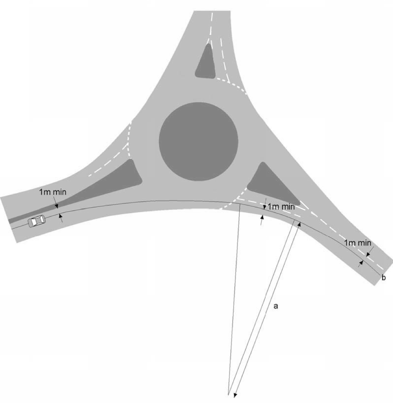
Appendix B. Roundabout capacity formula
This appendix provides the capacity formula utilised in the evaluation of a roundabout design. The formula shown forms the basis of ARCADY software.
B1 Roundabout capacity
B1.1 Roundabout capacity formula
The best predictive equation for the capacity of any roundabout entry (except those at grade-separated junctions and mini-roundabouts, see below) found by research to date is as follows:-
Equation B.1 Predictive equation for the capacity of roundabout entries except at grade separated junctions and mini-roundabouts
| where: | |
| QE | Entry flow in pcu/hour ( 1 HGV = 2 pcu ) |
| Qc | Circulating flow across the entry in pcu/hour |
| k | |
| F | 303x2 |
| fc | 0.210tD ( 1 + 0.2x2 ) |
| tD | 1 + 0.5 / (1+M) |
| M | exp {(D-60)/10} |
| x2 | v + (e-v) / (1+2s) |
| S | 1.6 (e-v) / l' |
| are geometric parameters defined in section 3 and ranges detailed in Tables B.1 and B.2 |
The value of QE will be:
- the solution of "k ( F - fc Q c)", when f cQc is less than or equal to F; but
- "0", when fc Qc is greater than F.
At grade separated junctions, there are differences of operation and the "F" term in the above equation becomes "1.11F" and the "fc" term becomes "1.4fc". These differences are incorporated in the ARCADY program.
The ranges of the geometric parameters input to the ARCADY database were as follows in Table B.1 (see Table B.2 in section B1.1.1 below for the recommended limits to be used in new design):-
| Parameter symbol | Parameter | Parameter range (in ARCADY) |
|---|---|---|
| e | entry width | 3.6 - 16.5 metres |
| v | approach half width | 1.9 - 12.5 metres |
| l' | average effective flare length | 1 - ∞ (metres) |
| S | sharpness of flare | 0.0 - 2.9 |
| D | ICD | 13.5 - 171.6 metres |
| entry angle | 0.0 - 77 (degrees) | |
| r | entry radius | 3.4 - ∞ (metres) |
Research for the original calculation above is contained in TRL SR 721 [Ref 13.I], this research was further expanded on in TRL RR 142 [Ref 12.I] to improve capacity modelling for large roundabouts and grade separated junctions using ARCADY.
Additionally, current ARCADY software has a queue simulation mode that considerably improves specific limitations of the original software. This queue simulation mode allows lane starvation to be evaluated so that it can be avoided in further roundabout design stages.
Guidance on the calculation for mini-roundabouts can be found in TRL AG 72 [Ref 7.I].
B1.1.1 Practical limits of geometric parameters
Trial designs in ARCADY should be calibrated where necessary to obtain operational efficiency by adjusting the entry widths and the effective length of flares. Whilst the formula above gives the range of the parameters for which the predictive equation is valid, the following list gives the normal practical limits of those parameters in a new design.
| Parameter symbol | Parameter | Parameter range (practical limits) |
|---|---|---|
| e | entry width | 4.0 - 15.0 metres |
| v | approach half width | 2.0 - 7.3 metres |
| l' | average effective flare length | 1.0 - 100.0 metres |
| D | ICD | 15 - 100 metres |
| entry angle | 10 - 60 degrees | |
| r | entry radius | 6.0 - 100.0 metres |
The circulatory carriageway width around the roundabout should be constant between 1.0 to 1.2 times the greatest entry width, subject to a maximum of 15 metres.
Sections 3, 4, 5, 6 and 7 provide specific requirements and advice for all of the geometric parameters.
B1.2 Entry angle measurement where distance between entry and exit exceeds 30 metres
The methods of measuring the entry angle at conventional large or small normal roundabouts are given in Section 3. For roundabouts, where the distance between the offside of an entry and the next exit is more than 30 metres and is approximately straight, the construction of the entry angle, , is illustrated in Figure B.1.
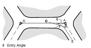
AD is parallel to the straight circulatory carriageway where A is the point of maximum entry deflection at the right hand end of the give-way line, and D is the point nearest to A on the median island (or marking) of the following entry.
The line BC is a tangent to the line EF, which is midway between the nearside kerb line and the median line or the edge of any median island on the offside, where this line intersects the "give way" line.
is measured as the acute angle between the lines BC and AD in Figure B.1.
Appendix C. Additional advice on provision of segregated left turn lanes and subsidiary deflection islands
This appendix provides additional advice regarding the decision process for providing segregated left turn lanes (SLTL) and subsidiary deflection islands (SDIs).
C1 SLTL flow chart
The decision process for the inclusion of an SLTL is shown in Figure C.1.
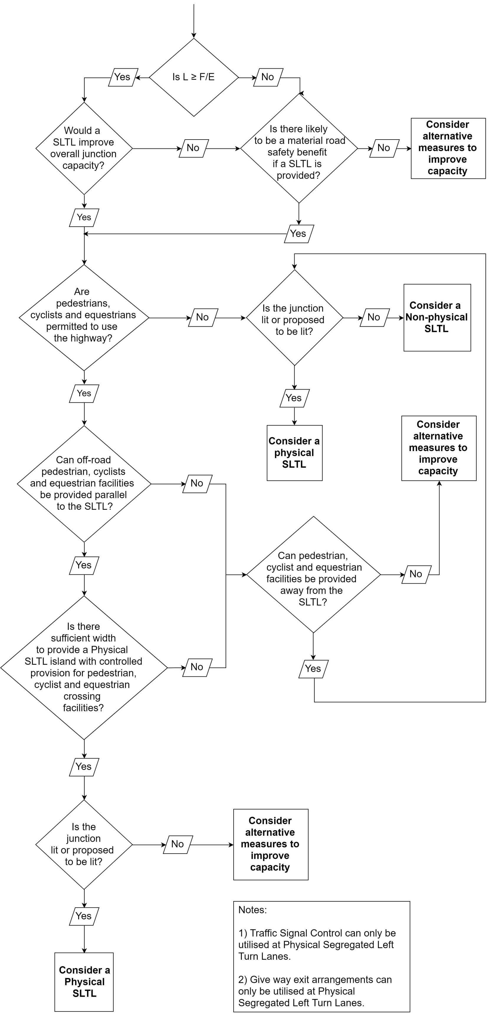
C2 SDI flow chart
The decision process for the inclusion of an SDI is provided in the flowchart in Figure C.2.
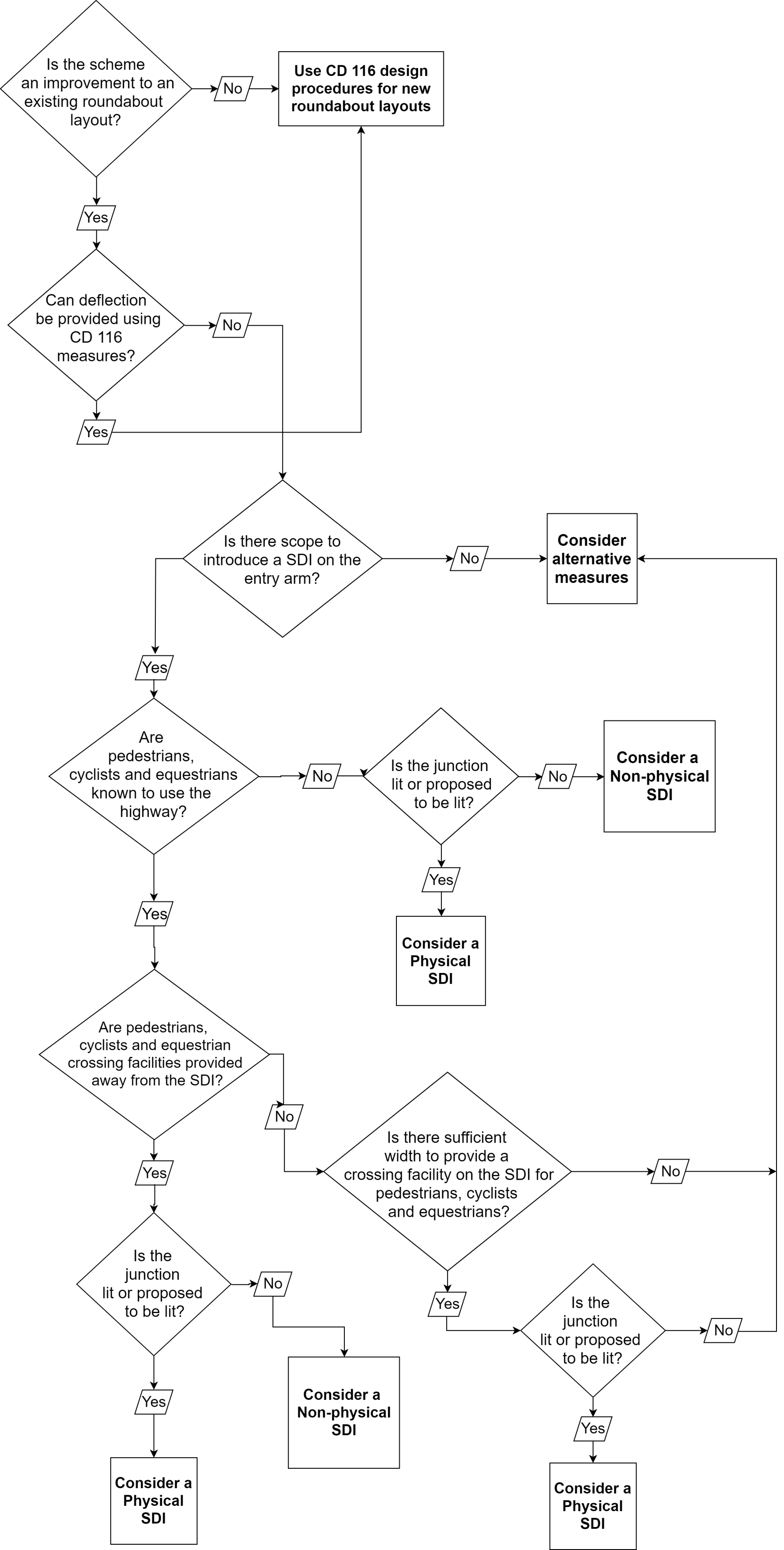
Appendix D. Additional advice for road markings and signs
This appendix provides additional advice regarding the design of road markings and signs on roundabouts, to give better understanding of design principles and to enable safe design.
D1 General principles
The associated traffic signs and road markings can significantly affect the safety and the capacity of a roundabout. Consequently, the need for and layout of traffic signs and road markings are an integral part of the design process.
D1.1 Application of principles
The flow chart in Figure D.1 shows the series of concerns or operational difficulties that may lead to road markings being used at a particular existing roundabout.
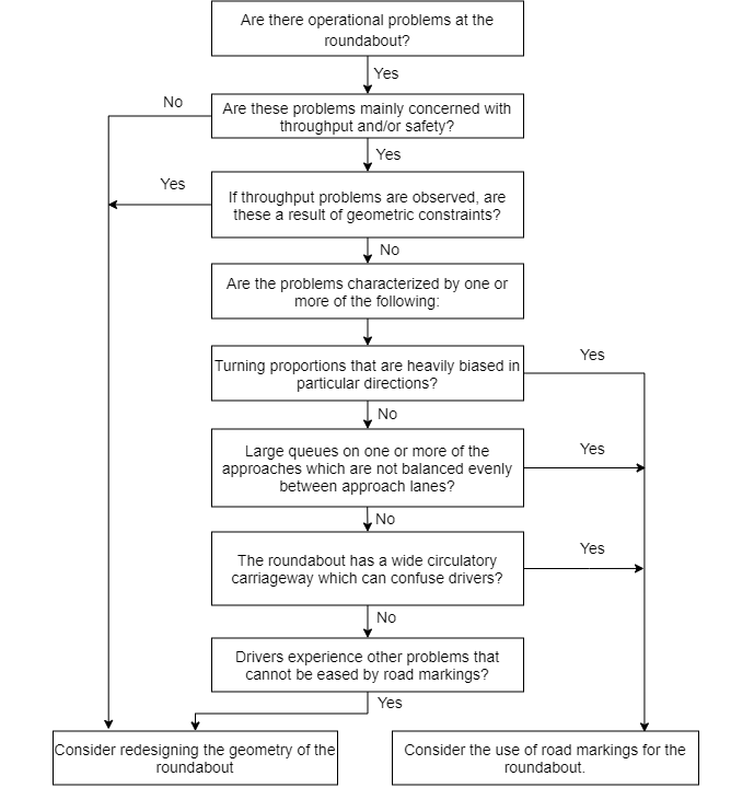
D2 Design principles
D2.1 General
The flow chart shown in Figure D.2 below outlines the main features of the design of road markings at roundabouts. Many of the features are dealt with separately, but it should be noted that the features are closely related and that the design of road markings at roundabouts is an iterative process.
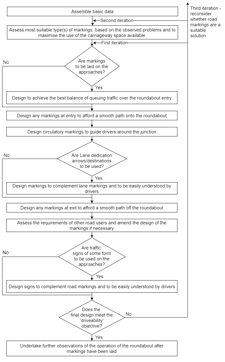
D3 Circulatory carriageway road markings
An initial assessment of the most suitable type of marking to address the identified main problems should be made. There are some elementary guidelines which assist in this choice.
- Concentric markings (see Figure D.3) are useful to encourage drivers to enter and circulate in two or more adjacent lanes. This increases the potential throughput in locations where this does not ordinarily occur.
- Concentric markings which divide the carriageway into more than two lanes have limited use on wide circulatory carriageways since they have been found to encourage the “tramline” effect. In this case, a driver may remain in a particular lane until reaching the desired exit, and then deviate across other circulating movements in order to leave the roundabout. This behaviour can increase the potential for side-to-side vehicular conflict on the circulatory carriageway.
- Partial concentric markings (see Figure D.4) can assist on wide circulatory carriageways by presenting drivers with clearly defined lanes within which to pass around the junction, and reduce the likelihood of drivers in the offside entry lane being forced towards the central island. The breaks in markings continuity allow vehicles to change lanes in advance of exits.
-
- At very large roundabouts, ensure that continuity between successive partial concentric markings and the number of circulating lanes is maintained in order to minimise driver confusion.
- Concentric-spiral markings (see Figure D.5) are useful in reducing conflicts between vehicles at the exits, where more than one exit lane is provided. This type of marking can be used with any number of circulating lanes.
- Spiral markings (see Figure D.6) are more appropriate on large roundabouts where they can be used to guide drivers around the roundabout to their desired exit, whilst maximising the use of the circulating space and reducing potential conflict between adjacent vehicles. The markings can also cater for heavily biased turning proportions, since the circulatory width may be divided according to traffic demand.
-
- Their use should only be considered where the circulatory carriageway has sufficient width to cater for two or more lanes of traffic. Where the size and shape of the roundabout is such that sharp manoeuvres be required between successive entries and exits when following the lanes, spiral markings may not be appropriate.
- U-turning vehicles are required to change lanes with spiral markings. Where there is a significant proportion of U-turning vehicles, hatching at the commencement of the spiral markings may be omitted.
- Road markings as per UKSI 2016/362 (TSRGD) [Ref 9.N]Diagram 1042, as well as coloured surfacing under hatched markings (highlighted in TSM Chapter 5), can be used to improve conspicuousness and discourage encroachment.
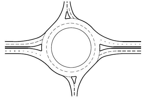
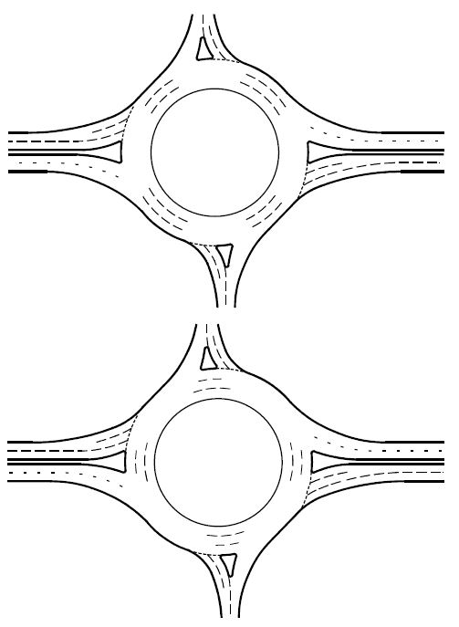
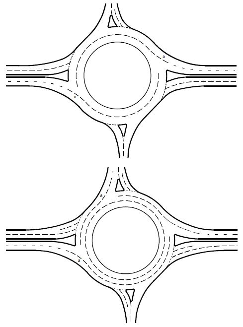
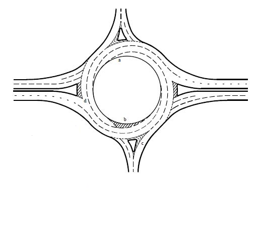
On Figure D.5, 'a' indicates markings are designed to lead the outermost lane off at the desired exit.
On Figure D.6 which illustrates spiral markings:
- 'a' indicates lane developed from the central island;
- 'b' indicates lane developed from the central island with hatched markings;
- 'c' indicates the outermost lane that leads directly off; and,
- 'd' indicates the driver in the middle lane afforded a choice of exit.
Spiral markings are developed from the central island by means of line markings, or by hatched markings until a full lane width is available.
Spiral line markings are appropriate on normal roundabouts, but where the inscribed circle and central island are small and/or the number of arms is high, the first two or three markings leading to the full lane width can be omitted.
Spiral markings are broken adjacent to the roundabout entries so that drivers entering the roundabout are not required to cross the markings. Lane markings placed across or opposite entries are liable to become worn in a short time due to the traffic crossing them. In such circumstances, consideration may be given to markings less susceptible to wear (see Figure D.7).