Design Manual for Roads and Bridges


General Principles & Scheme Governance
General Information
GG 117 The design and implementation of temporary traffic management and road works
(formerly N/A)
Version 1.0.0
Summary
This standard gives the requirements for the design and implementation of temporary traffic management
National Variation
This document has associated National Application Annexes providing alternative or supplementary content to that given in the core document, which is relevant to specific Overseeing Organisations. National Application Annexes are adjoined at the end of this document.
Feedback and Enquiries
Users of this document are encouraged to raise any enquiries and/or provide feedback on the content and usage of this document to the dedicated National Highways team. The online feedback form for all enquiries and feedback can be accessed at: www.standardsforhighways.co.uk/feedback.
This is a controlled document.Latest release notes
| Document Code | Version number | Date of publication of relevant change | Changes made to | Type of change |
|---|---|---|---|---|
| GG 117 | 1.0.0 | January 2024 | Core document, England NAA, Northern Ireland NAA, Scotland NAA, Wales NAA | Change to policy, major revision, new document development |
| Version 1.0.0; Publication January 2014] New document; gives the requirements for the design and implementation of temporary traffic management | ||||
Previous versions
| Document Code | Version number | Date of publication of relevant change | Changes made to | Type of change |
|---|
Foreword
Publishing information
This document is published by National Highways.
Contractual and legal considerations
This document forms part of the works specification. It does not purport to include all the necessary provisions of a contract. Users are responsible for applying all appropriate documents applicable to their contract.
Introduction
Background
This standard is introduced as part of an objective to support the adoption of new guidance and best practice into application as quickly as possible. This will supplement Traffic Signs Manual Chapter 8 TSM Chapter 8 [Ref 3.I], which will continue to retain the majority of guidance and best practice relating to road works and temporary situations.
The Traffic Signs Manual chapters are subject to cyclical updates, around every three to four years at present, therefore leaving a significant period of time between publications. Currently there are limited other opportunities to disseminate new guidance and best practice relating to road works and temporary situations into industry for consideration.
This standard will ensure that industry, customers and stakeholders will be facilitated to realise the benefits of new practice and guidance more efficiently. The content will largely be located within the appendix of this standard, as it will be the decision of temporary traffic management (TTM) designers and schemes as to when it is incorporated into their works, in line with current working practices. However, it should better support the industry in making decisions relating to the design and operation of TTM given the continued updates to guidance through this mechanism.
It is envisaged that content situated in this standard will transfer into future iterations of TSM Chapter 8 [Ref 3.I]where applicable. This will be determined via existing governance and procedures and would need to be consented to by the devolved administrations and other identified stakeholders.
Assumptions made in the preparation of this document
The assumptions made in GG 101 [Ref 4.N] apply to this document.
Abbreviations and symbols
| Abbreviation | Definition |
|---|---|
| ALARP | As low as reasonably practicable |
| DfT | Department for Transport |
| EMCC | Enhanced mobile carriageway closure |
| TFZ | Traffic-free zone |
| TSM | Traffic Signs Manual |
| TSRGD | The Traffic Signs Regulations and General Directions UKSI 2016/362 (TSRGD) [Ref 7.N] |
| TTM | Temporary traffic management |
Terms and defintions
| Term | Definition |
| Alarm | An alarm, in conjunction with the incursion warning system, providing a non-verbal audible and flashing red visual warning of an incident such as an incursion, or that the EMCC vehicle is at the boundary of the safety zone. |
| Alert | An alert, in conjunction with the incursion warning system, providing a non-verbal audible and visual flashing blue notification that the EMCC is 500 m prior to the working area. |
| Authority | A highway authority responsible for the condition and maintenance of the public road and/or a traffic authority responsible for the free-flowing movement of traffic on a network. |
| Diagram | Where a 'Diagram' is referred to, it is in reference to the diagram number within the Traffic Signs Regulations and General Directions UKSI 2016/362 (TSRGD) [Ref 7.N] |
| Downstream | The part of the carriageway(s) where traffic is flowing away from, or is beyond, the identified area of activity/work. |
| Enhanced mobile carriageway closure (EMCC) | A contractor-led technique enhancement of the existing mobile carriageway closure technique. |
| EMCC vehicle | A vehicle, equipped with authorised EMCC vehicle signing, incursion warning system, two-way radio and CCTV cameras which, when aligned with or without other such vehicles, forms a mobile carriageway closure creating the traffic free zone. |
| Free flow traffic | The traffic is unhindered by an EMCC closure and able to travel at the speed suitable for the traffic conditions. |
| Incursion | Any entry of a vehicle into the traffic-free zone during the operation of the EMCC. |
| Incursion warning system | A digital system that creates and delivers a non-verbal audible and visual warning alert and/or alarm to workers in the working area when an incursion has occurred. This is either activated automatically or manually by the operator of the EMCC vehicle. |
| Operator | The person, in the EMCC vehicle, who is responsible for implementation and co-ordination of the EMCC operation, creating the temporary traffic-free zone. |
| Platoon | The group or cluster of slower moving traffic upstream of the traffic free zone created by the EMCC vehicle(s) slowing traffic from free flow traffic conditions. |
| Traffic free zone | The section of carriageway ahead of the enhanced mobile carriageway closure vehicle(s) that is clear of traffic, including the area free of traffic upstream of the longitudinal safety zone and working area. |
| Two-way radio | A dedicated secondary means of verbal communication between all EMCC operators and all working areas protected by this technique downstream of the EMCC vehicle(s). |
| Upstream | The part of the carriageway(s) where traffic is flowing towards, or is prior to, the identified area of activity/work. |
| Working area | The area occupied by the works themselves. |
| Working window | The time during which the working area is free from non-works traffic. |
| 85th percentile speed | The term describing the normal likely speed of traffic on a road. |
1. Scope
Aspects covered
1.1 The requirements in this document shall be used for the design and operation of temporary traffic management (TTM) and road works on motorways and all-purpose trunk roads.
Implementation
1.2 This document shall be implemented forthwith for the design of road works and the operation of TTM on all highway schemes on the Overseeing Organisation's motorway and all-purpose trunk roads according to the implementation requirements of GG 101 [Ref 4.N].
Use of GG 101
1.3 The requirements contained in GG 101 [Ref 4.N] shall be followed in respect of activities covered by this document.
2. Requirements for the design and operation of temporary traffic management and road works
General requirements
2.1 Road works and temporary traffic management (TTM) shall be designed and operated to be both safe and efficient.
NOTE The principles of "safe and efficient" traffic management are outlined in the Traffic Signs Manual TSM Chapter 8 [Ref 3.I].
2.1.1 In addition to TSM Chapter 8 [Ref 3.I], DMRB standards and other relevant publications, road works may be designed and operated in line with the additional guidance detailed in the appendices of this core document.
2.1.2 Additional guidance detailed in the appendices of this core document may be used when designing and planning the operation of TTM.
2.2 All relevant, available guidance and standards relating to TTM design and operation shall be assessed when designing road works or temporary situations, as this will help support safe systems of working.
NOTE 1 TTM design and operations are underpinned by recognised training courses and qualifications relevant to the activity selected.
NOTE 2 It is for the TTM designer to adopt, adapt or develop the road works design and/or TTM operational practices to suit the actual site conditions.
2.3 Road works shall be designed on a site-specific basis.
Health and safety
2.4 Safe systems of work, including safety risk assessments, design review and design approval shall be developed and followed in the design of TTM.
2.5 The level of safety risk management for road works design and TTM operations shall be determined and informed by a safety risk assessment.
2.6 When designing, operating and planning road works the safety of road workers, road users and all populations affected directly or indirectly by the works shall be clearly demonstrated.
NOTE “Populations” are defined in GG 104 [Ref 5.N], with additional guidance provided in Traffic Signs Manual TSM Chapter 8 [Ref 3.I].
2.7 The risk to road workers must be managed in accordance with the requirements of the Health and Safety at Work etc Act UKPGA 1974/37 [Ref 3.N]and, where applicable, the Health and Safety at Work (NI) Order 1978 NIOC 1978/1039 [Ref 2.N].
NOTE Safe design and operations can be demonstrated via documentation such as safety risk assessments and safe systems of works.
2.8 Road works shall be designed using the principles of ALARP when assessing risk.
3. Normative references
The following documents, in whole or in part, are normative references for this document and are indispensable for its application. For dated references, only the edition cited applies. For undated references, the latest edition of the referenced document (including any amendments) applies.
| Ref. | Document |
|---|---|
| Ref 1.N | BSI. BS EN 12899-1, 'Fixed, vertical road traffic signs. Fixed signs (Designated Standard - CPR)' |
| Ref 2.N | National Archive. NIOC 1978/1039, 'Health and Safety at Work (Northern Ireland) Order 1978' |
| Ref 3.N | National Archives. UKPGA 1974/37, 'Health and Safety at Work etc. Act' |
| Ref 4.N | National Highways. GG 101, 'Introduction to the Design Manual for Roads and Bridges' |
| Ref 5.N | National Highways. GG 104, 'Requirements for safety risk assessment' |
| Ref 6.N | National Archives. UKPGA 1984/27, 'Road Traffic Regulation Act' |
| Ref 7.N | National Archive. UKSI 2016/362 (TSRGD), 'The Traffic Signs Regulations and General Directions' |
4. Informative references
The following documents are informative references for this document and provide supporting information.
| Ref. | Document |
|---|---|
| Ref 1.I | National Highways. RtB 27, 'Raising the Bar 27 - Preventing and managing incursions ' |
| Ref 2.I | https://www.gov.uk/government/collections/traffic-signs-signals-and-road-markings#traffic-signs-regulations. DfT. Traffic signs images and drawing, 'Road traffic signs, signals and road markings regulations, guidance and images' |
| Ref 3.I | TSO. TSM Chapter 8, 'Traffic Signs Manual Chapter 8 - Traffic Safety Measures and Signs for Road Works and Temporary Situations' |
Appendix A. Enhanced mobile carriageway closure
A1 Overview of enhanced mobile carriageway closure
Traffic Signs Manual TSM Chapter 8 [Ref 3.I]provides guidance for those responsible for the design and operation of temporary traffic management (TTM). It is expected that those persons looking to utilise the enhanced mobile carriageway closure (EMCC) outlined within this document are suitably trained and possess the relevant qualifications to adopt this technique. They should also be both experienced and familiar with the principles of TSM Chapter 8 [Ref 3.I] and TTM.
On dual carriageway roads, including motorways, some traffic management tasks and works operations may need to be conducted on the carriageway using a temporary traffic free zone (TFZ), where the road is clear of passing traffic for a short period of time. The installation or movement of a short length of coning and signing to change the configuration of a TTM layout during road works, which takes less than 5 minutes, is one such example where this may be required.
The mobile carriageway closure (MCC) and the convoy control vehicle technique are existing and established techniques with guidance outlined in TSM Chapter 8 [Ref 3.I]. They are operated by the traffic Authority or contractor using signs to provide warnings and information relating to restrictions or changes in carriageway conditions. The traffic signs used as part of these techniques are done so by the powers provided by Sections 64/65 of the Road Traffic Regulation Act 1984 UKPGA 1984/27 [Ref 6.N]. EMCC signs require authorisation for each highways/road Authority they are used on. At the time of publication the only authorisation is for National Highways’ roads. For their use on other Overseeing Organisation’s roads one should check with the relevant national body responsible for signs authorisations.
The EMCC, as described in this document, is a development of both the aforementioned techniques. Whilst the EMCC includes the word "closure" its use does not include planned closures of the carriageway by bringing traffic to a stop (see Section A2).
The implementation and selection of any technique for an operation should be considered and evaluated as part of the planning phases. Both contractors and the Authority should be aware that the EMCC is to be considered as a potential method of working alongside other existing and established TTM techniques.
It is essential that the use of the EMCC technique does not transfer risk from road workers to road users. The principles of ALARP need to be adhered to as outlined in TSM Chapter 8 [Ref 3.I].
Temporary traffic free zones have traditionally been created by requesting police or traffic officer support to implement a rolling road block. With the emergence of the EMCC, requests for police or traffic officers to support planned work activities should begin to be limited to unplanned incidents.
The traffic free zone created by the EMCC allows for traffic management operations to be conducted in a sterile area. EMCC can be used for the installation, maintenance, switching or removal of any temporary traffic management layout and pre-setting of equipment. It can also be used to support the maintenance of a traffic management system such as when live lane working is required for crossing a carriageway to maintain traffic management equipment, managing displaced traffic management equipment and retrieving debris, all of which are expected activities occurring as part of planned works.
The EMCC technique can be used for short-term works operations to avoid a planned total closure of the carriageway. This technique may be useful for the installation of TTM exit slip road detail, as it eliminates the need for a temporary short term exit slip road closure.
The EMCC technique described in this document may be suitable for use on dual carriageways and motorways with up to four lanes. Where used on four lane carriageways up to a maximum of one additional lane from a junction (e.g. a parallel merge) can be incorporated. This technique may also be used on slip or link roads where safe and practicable to do so.
A2 Principles of the enhanced mobile carriageway closure
A2.1 The enhanced mobile carriageway closure operation
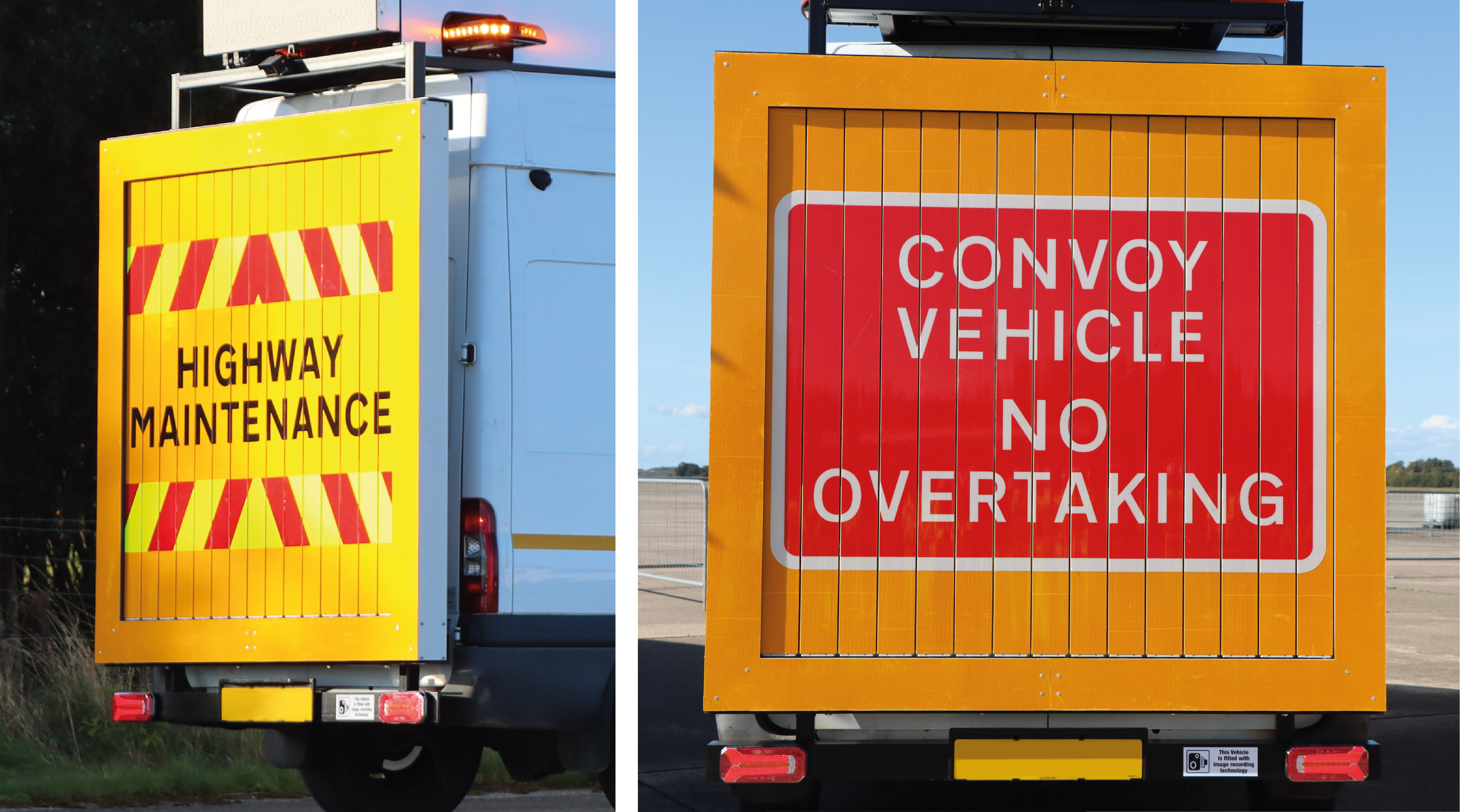
A traffic free zone is created by one or more EMCC vehicles which manoeuvre within normal free flow traffic conditions, initially showing rear signing to Diagram 7404 ‘HIGHWAY MAINTENANCE’ with chevrons and rear beacons on (Figure A.1 Aspect A).
The EMCC vehicle will then change to show rear signing formed of an upper panel of the red 'X’ and a lower panel of the sign to Diagram 7029 “CONVOY VEHICLE NO OVERTAKING with rear beacons off (see Section A6) to create a lateral closure across the carriageway. The speed of the EMCC vehicle is then gradually and steadily reduced from the 85th percentile speed of private cars and light vehicles to around 10 mph.
It is this slowing of traffic at a controlled rate which creates a traffic free zone downstream between the EMCC vehicle(s) and the traffic moving away at normal speed in front of the EMCC vehicle, creating time for the works operation to be undertaken. To ensure the traffic free zone is a safe and sterile area, any hard shoulders, emergency areas or other identified stopping places for vehicles need to be confirmed as clear, prior to the work commencing.
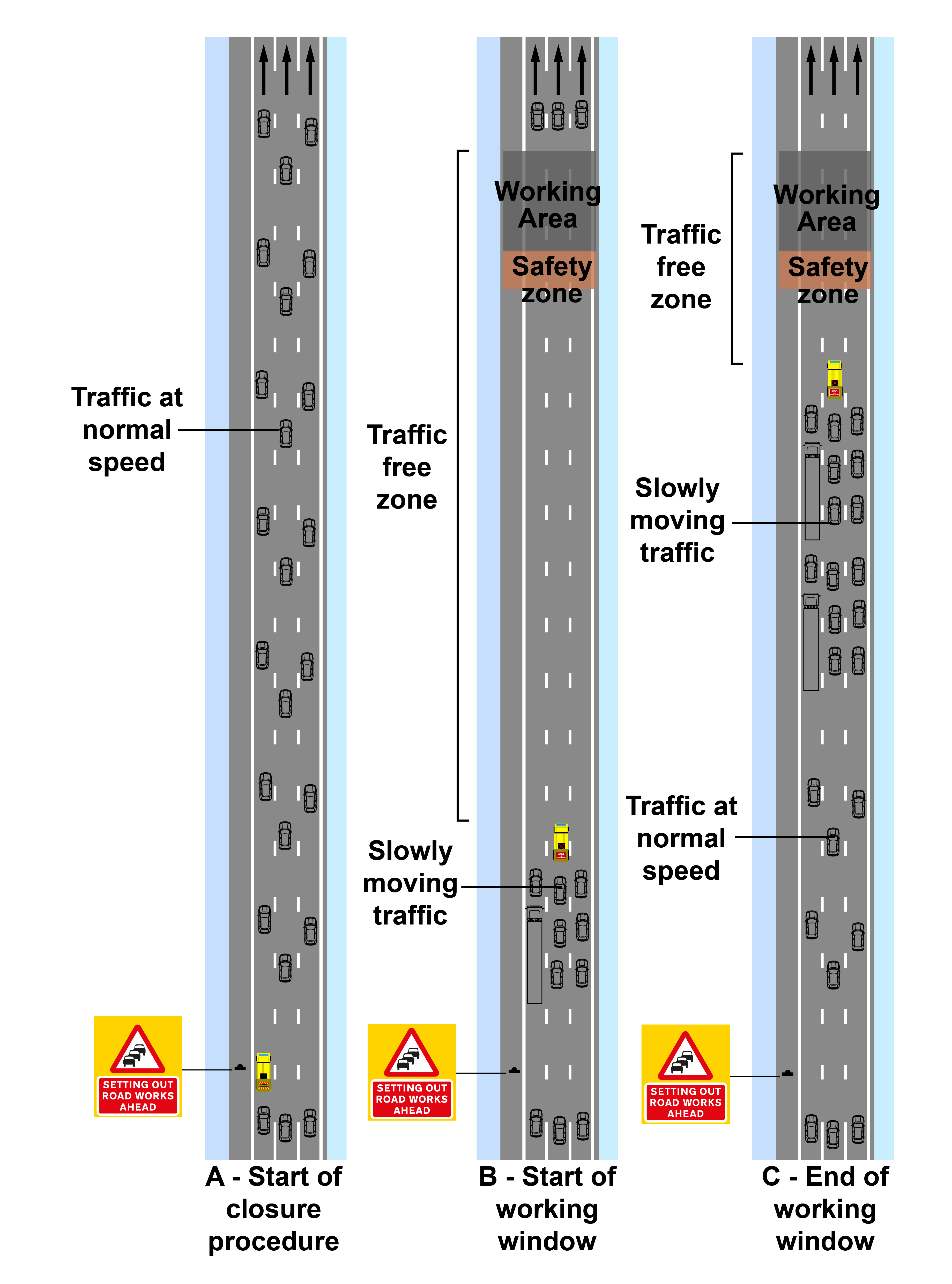
When the last of the traffic downstream of the EMCC vehicle has passed the proposed working area, (Figure A.1 Aspect B), work on the carriageway can commence in the traffic-free zone.
The EMCC vehicle(s) moves towards the working area (Figure A.1 Aspect C) travelling at a reduced speed of around 10 mph (see Figure A.2). Before the EMCC vehicle(s) reaches a minimum of 200 m upstream of the working area, the carriageway is restored to a safe arrangement for the passage of traffic and personnel located in a place of relative safety.
When the relevant operation has been confirmed as completed or suspended via radio communication it is essential that the EMCC vehicle(s) steadily build up speed (to between 30 to 40 mph). This is to space out the traffic behind the EMCC vehicle and allow traffic to change lanes, if required, before resuming normal speed. When the EMCC vehicle(s) has passed through the area of works operation for which the EMCC has been put in place, they will change to showing the rear signing to Diagram 7404 ‘HIGHWAY MAINTENANCE’ and chevrons. They then move to the left-hand lane of the carriageway to allow traffic to pass. The operation is then complete.
A2.2 Unplanned stops
An EMCC is not permitted to bring traffic to a planned stop to allow a works operation. Traffic may only be brought to a controlled stop in the event of an incident or emergency arising during the operation. Where no official confirmation, via radio communication, is received from the works team that the working area is clear from personnel at the boundary of the safety zone (a minimum of 200 m prior to the working area) then the EMCC vehicle slowly brings traffic to an unplanned stop around 100 m from the working area.
Where an unplanned stop occurs, the relevant control room needs to be contacted immediately. Subsequently, the Authority is informed whenever traffic has been brought to a stop through this technique and the event recorded as an unplanned incident. The Authority should also be informed of any near misses, incursions or incidents, prior to, during or shortly after the EMCC which may be related to the operation. Such events are to be recorded by the Authority.
A2.3 Communications
Work in a traffic free zone needs to be supported by a functioning digital incursion warning system as one of the primary means of managing the residual risk of any vehicle passing the EMCC. A dedicated two-way radio system also needs to be provided as a supporting secondary means of verbal communication between the EMCC vehicle and the working area.
Multiple crews can work in one traffic free zone. Where more than one crew works in one traffic free zone it is essential that they are connected to the same two-way radio communication channel and incursion warning system. When the EMCC vehicle(s) activates an alarm or communicates with the working areas all crews will receive the same message simultaneously.
A2.4 Digital incursion warning system
The use of the EMCC technique is underpinned by using a digital incursion warning system activated when there is breach by any vehicle, inclusive of emergency vehicles. The incursion warning system needs to be manually activated by the EMCC vehicle operator which immediately delivers an audible and visual alarm, warning of an errant vehicle to all persons in the working area, allowing them to move to a place of relative safety. The EMCC vehicle may need to continue to proceed at the reduced speed up to the proposed working area, until the operation has been confirmed as suspended.
The warning system will need to automatically deliver an alert at 500 m prior to the approach working zone and then an incursion alarm at 200 m prior to the safety zone (See Figure A.3). 200 m is the minimum distance for the final automatic alarm. Where a larger safety zone is implemented e.g. 300 m, the final alarm should be aligned to the same distance of 300 m.

The digital incursion warning system is automatically activated when the sign on the rear of the EMCC vehicle changes to Figure A.8. When the rear of the vehicle is showing signing to Figure A.9 it is deactivated. Where the EMCC vehicle is travelling at a speed equal to, or greater than, 30 mph the alert at 500 m will still sound, but the automatic alarm at 200 m will not.
In the unlikely event of a total communication failure, including the failure of the digital incursion warning system and radio communication during the operation, the EMCC is not to be aborted as this may compromise the safety of the personnel in the working area. The EMCC vehicle(s) should proceed with caution at the reduced speed towards the working area. If the carriageway is not clear of personnel and/or equipment then the EMCC comes to an unplanned stop.
A2.5 Multiple passes for one works operation
Works need to be planned to ensure the number of passes conducted are kept to an absolute minimum, to reduce the impact on the road network. Consultation with the Authority is generally required if more than two passes are anticipated to establish traffic management layout on one carriageway. Where appropriate, pre-placement of traffic management equipment may be undertaken to reduce the consecutive number of passes to establish the works (see Figure A.4).
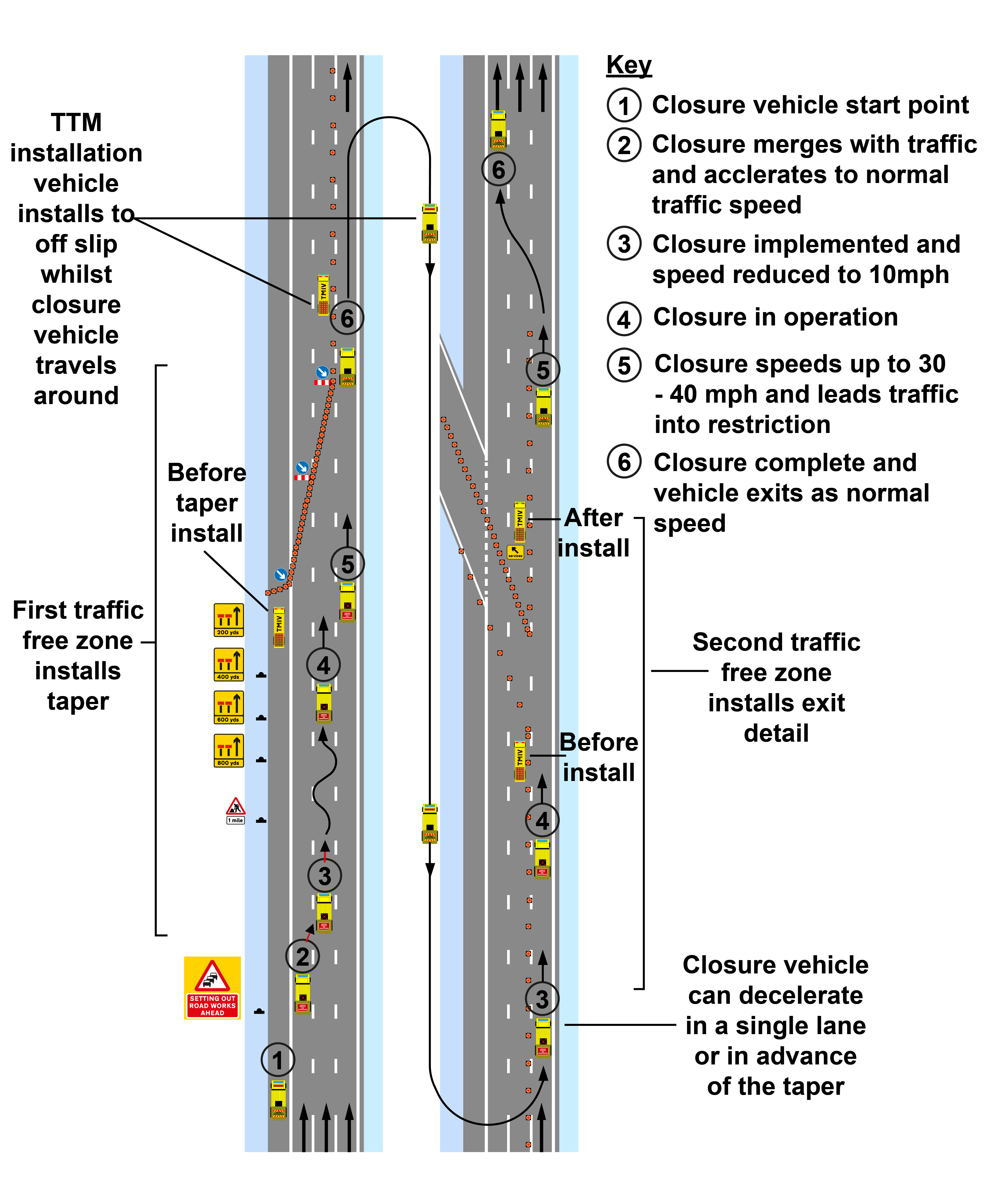
Works operations need to be capable of being left in a state that is safe to both road users and road workers where more than one pass is required.
A3 Design and planning considerations
This document does not distinguish between the differing features of a carriageway such as a 'controlled motorway', 'dynamic hard shoulder' or 'all lane running'. These characteristics need to be assessed at the design and planning stage of the works, along with any risk mitigations based on the site.
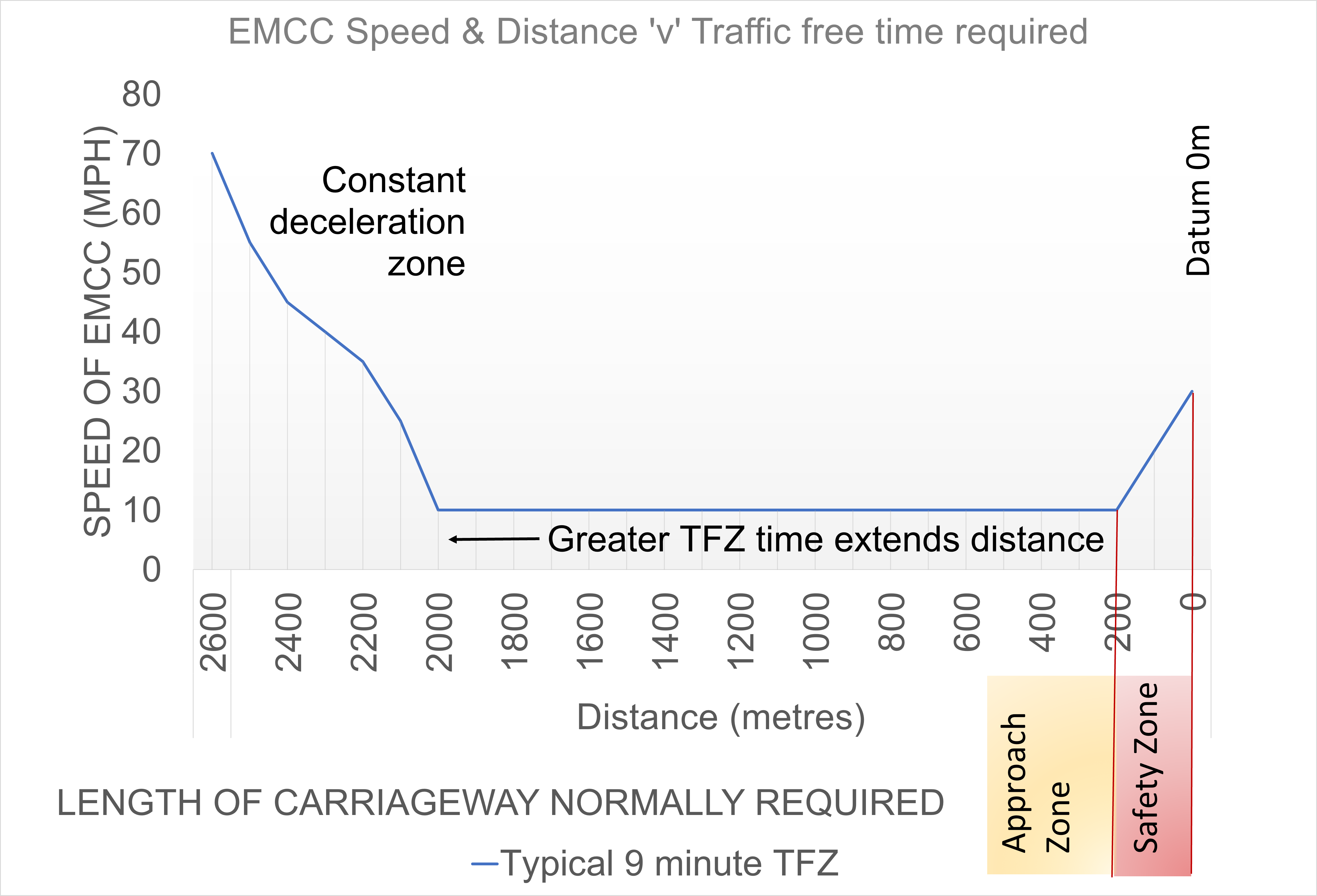
In general, the duration required to create the sterile area should be planned to generally remain in the 5-to-7-minute range, and should not exceed 9 minutes, before the EMCC vehicle starts to accelerate from 10 mph to release traffic back to free flow conditions.
At an average speed of 10 mph the EMCC vehicle and traffic behind it will cover around 300 m every minute. The distance upstream, and therefore the traffic free zone, needs to be identified based on;
- the 500 m area of deceleration at the EMCC start point;
- the number of minutes required for the working window multiplied by 300 m; and,
- plus a minimum 200 m of longitudinal safety zone.
Maintaining a minimum longitudinal safety zone of 200 m between the working area and the EMCC was shown in the trials to support a safe system of working, although a safety risk assessment should determine the required distance.
A traffic sign arrangement consisting of signs to Diagram 584 and Diagram 7003.1 UKSI 2016/362 (TSRGD) [Ref 7.N] (see Section A6) need to be erected upstream of the EMCC start point on all approach carriageways including slip and link roads when using the technique (see Figure A.5).
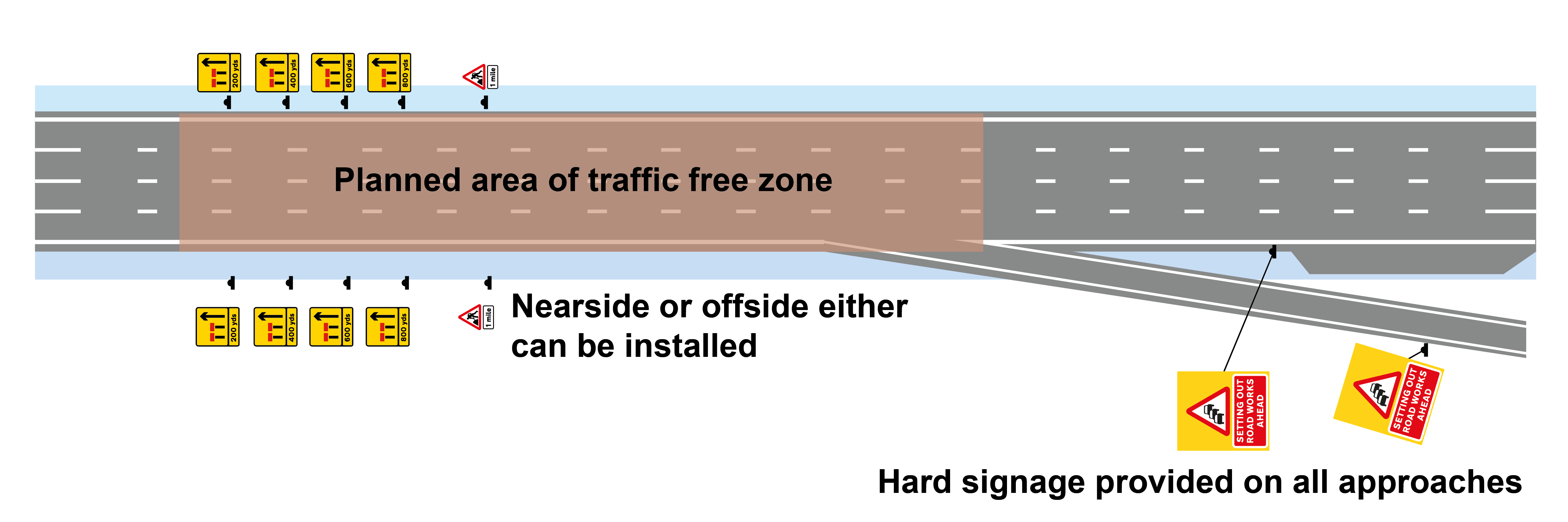
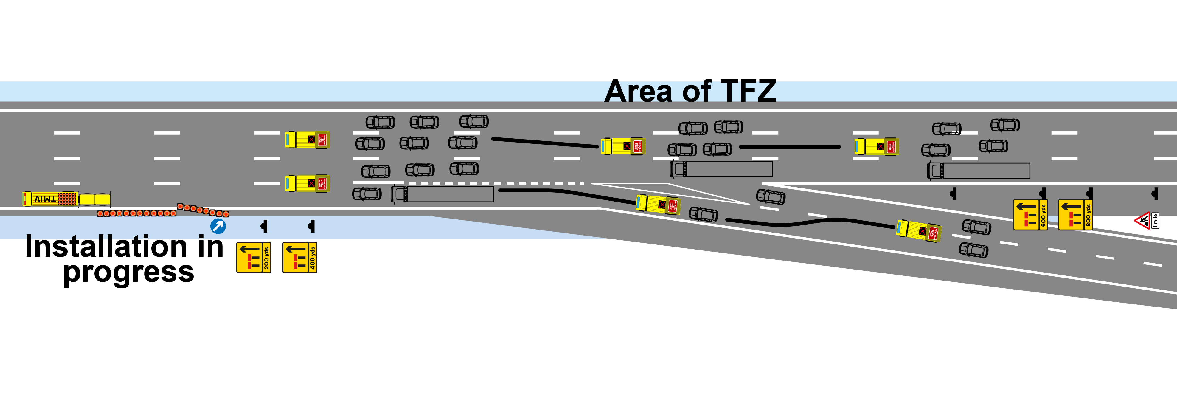
The presence of features such as entry slip roads or lane gain/drops within the traffic free zone between the working area and EMCC start point should be identified, and traffic control measures implemented. This can include a slip road closure, or additional EMCC vehicles being provided and coordinated to merge to continue downstream of an entry point (Figure A.6). TSM Chapter 8 [Ref 3.I] provides further detail and guidance on closing access junctions as part of TTM operations.
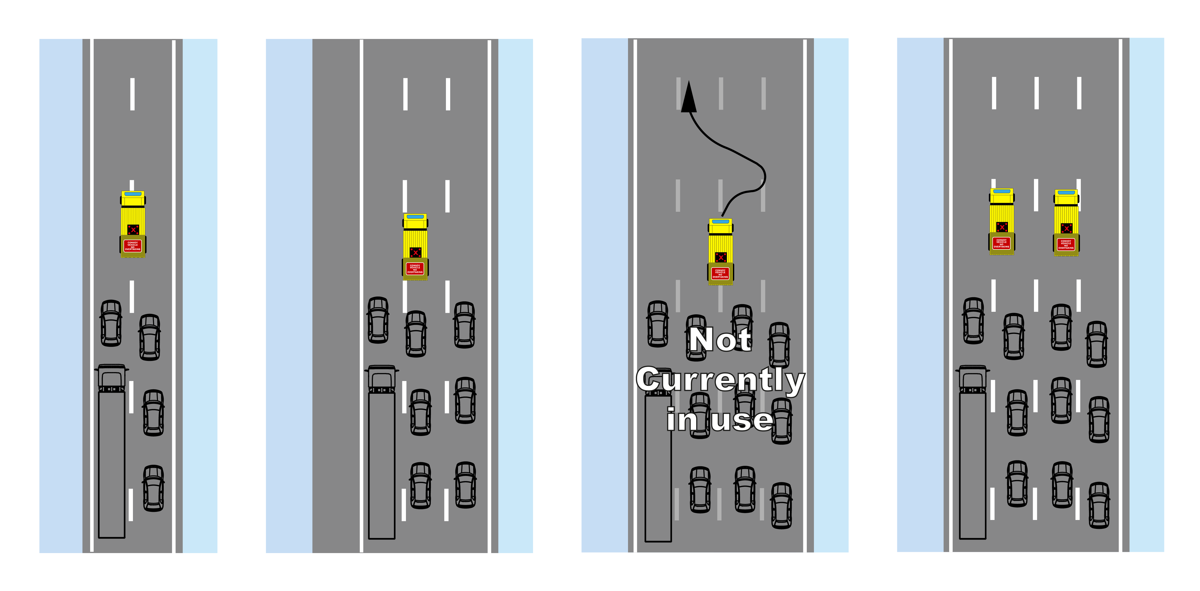
The EMCC vehicle may straddle lanes when creating a traffic free zone as the red 'X’ of the upper panel is not lane specific. (Figure A.7)
| Number of lanes | Minimum number of EMCC vehicles |
| 2 lanes | 1 |
| 3 lanes | 1 |
| 4 lanes | 2 |
The minimum number of EMCC vehicle(s) used needs to comply with Table A.1.
| Road type | HGV percentage | |||||
| 5% | 10% | 15% | 20% | 25% | 30% | |
| 2+ lane all-purpose dual carriageway | 1620 | 1560 | 1490 | 1430 | 1370 | 1310 |
| 2+ lane motorway | 1800 | 1730 | 1660 | 1590 | 1520 | 1470 |
| 2 + lane suburban dual carriageways | 1620 | 1560 | 1490 | 1430 | 1370 | 1310 |
A3.1 Traffic flow and volumes
When installing and removing TTM, this technique can be suitable for use in traffic conditions that exceed the definition of low traffic flow as defined by TSM Chapter 8 [Ref 3.I]. The designer needs to assess the likely capacity of the traffic management system after installation of the TTM using Table A.2, to decide a time to commence use of the technique to decelerate traffic from normal traffic speed.
Suitability of the technique and when it can be used will be determined by the designer and is subject to a risk assessment. This technique is less suitable for use where traffic volumes are generally less than 400 vehicles per hour, irrespective of the number of lanes remaining open, as there can be larger gaps in approaching traffic leading to delays in forming the EMCC.
When removing traffic management at night-time, contractors may need to wait until traffic arriving in groups exceeding 200 vehicles per hour or free flow traffic conditions of over 400 vehicles per hour spread over all lanes.
Safety of the platoon is maximised when the EMCC vehicle(s) progressively and steadily decelerates traffic from the 85th percentile speed of private cars and light vehicles to the lowest speed required to create the traffic free zone.
When work is confirmed as completed and it is safe to proceed, traffic is steadily led back to between 30 and 40 mph for a short period before the traffic controlled by the EMCC vehicle is released. Sudden deceleration(s) and acceleration(s) of traffic should be minimised.
Safety risk assessments support the decision making process to determine the most appropriate traffic management and on-site work activity. Where EMCC is selected, it is essential to include reference to its use during the road space booking and coordination process, and contractor liaison, with the relevant Authority and control room representatives.
A contractor can create a traffic free zone at a location of planned works for any task between the first advanced warning sign and the end of road works signs. Where the task is at the extremities of the advance zone the technique can be implemented upstream of the first sign location.
Road space does not need to be extended beyond the parameters normally booked when using the technique, as Part 1 of TSM Chapter 8 [Ref 3.I]Table 3.3 “Distance between sites” normally provides sufficient space. However, the Authority needs to be consulted during the planning of the works to ensure that impact to the network is managed and coordinated as part of the risk assessment.
A Temporary Traffic Regulation Order (TTRO) is not required to use this technique, but a TTRO may be required for the road works.
A4 Operator and staff training
When undertaking an EMCC operation the operator of the EMCC vehicle needs to be a competent, qualified individual and they will have completed a recognised training course in the use and operation of the EMCC. It is essential that regular monitoring of EMCC operator performance occurs.
As with all work instructions and operations taking place on a live carriageway a briefing and equipment testing takes place before the event. Briefing and testing on the EMCC will normally include items such as communication protocols and time constraints, the incursion warning system and two-way radio equipment prior to use. This needs to be covered as part of the risk assessment for the operation.
Where an EMCC vehicle is not used as part of an EMCC operation, such as for welfare facilities only, the operator is not required to have completed the EMCC training.
A5 Signing
A5.1 Enhanced mobile carriageway closure vehicle signing
The EMCC vehicle(s) is a specially adapted vehicle displaying a sign arrangement that is authorised for use in connection with the technique. Where the authorised sign is correctly displayed and used it is an offence for a member of the public to overtake the EMCC vehicle.
The authorised vehicle mounted sign arrangement consists of a lower panel sign to Diagram 7029 ‘CONVOY VEHICLE NO OVERTAKING’ . This is supported by an upper panel consisting of an active light source displaying a steady red 'X’ with alternating lamps (see Section A6) for when an EMCC is in operation.
Deviation from the design of the lower panel including its dimensions, vinyl specification and size of the surrounding yellow lower panel from what is authorised would not be considered a traffic sign. The upper panel arrangement can only be altered to another manufacturer's red 'X’ where there is an authorisation of the active light source.
The sign arrangement needs to be capable of being operated from the cab of an EMCC vehicle. In the case of equipment failure the sign needs to be capable of being manually returned to Diagram 7404 UKSI 2016/362 (TSRGD) [Ref 7.N].
When the EMCC vehicle is not used as part of the operation the rear sign shows Diagram 7404 UKSI 2016/362 (TSRGD) [Ref 7.N] ‘HIGHWAY MAINTENANCE’ sign and chevrons (see Section A6) with the upper panel being blank.
A5.2 Approach signing
The sign arrangement shown in Section A6 replaces the requirement to display the Diagram 7003.1 ‘WORKFORCE IN ROAD-SLOW’ sign when this technique is used to create a traffic free zone.
When a technique is being used to install a traffic management system it is essential that the EMCC vehicle does not pass the lane indication signs to Diagram 7202.1 UKSI 2016/362 (TSRGD) [Ref 7.N] until those signs display the correct indication of the layout of the reduction in lanes being installed. The traffic management contractor needs to provide adequate resources to achieve this.
When motorway incident detection and signalling (MIDAS) is available it should be used but disabled downstream of the first cone of the taper. However, MIDAS needs to remain in operation upstream of the first cone, as is the current normal operational practice in road works.
A5.3 Variable signs and signals (VSS) with the enhanced mobile carriageway closure
In general, when this technique is used the overhead VSS commonly set to support the presence of stationary traffic management vehicles in live traffic lanes do not need to be set. The signals normally consist of a series of lane usage indications and reduced speed mandatory limits but as this technique eliminates traffic from the hazard of stationary traffic management vehicles and travels at a much lower speed, the signal indications are superfluous.
On those occasions where VSS are used as the primary advanced signs for road works, replacing roadside advance signs, the signing methodology outlined in this section will need to be adapted appropriately and the requirements of D6.13.13 in TSM Chapter 8 Part 1 and U2.15.29 to .32 in TSM Chapter 8 Part 3 TSM Chapter 8 [Ref 3.I]will need to be met. In circumstances where signals are set, conflicting signs and messages to the road user need to be eliminated.
The contractor notifying or requesting permission to commence the EMCC with the relevant control room establishes a clear understanding whether the VSS are required. Reference should be made in communications to the control room operator that the “enhanced mobile carriageway closure” is being used.
A6 Sign arrangements
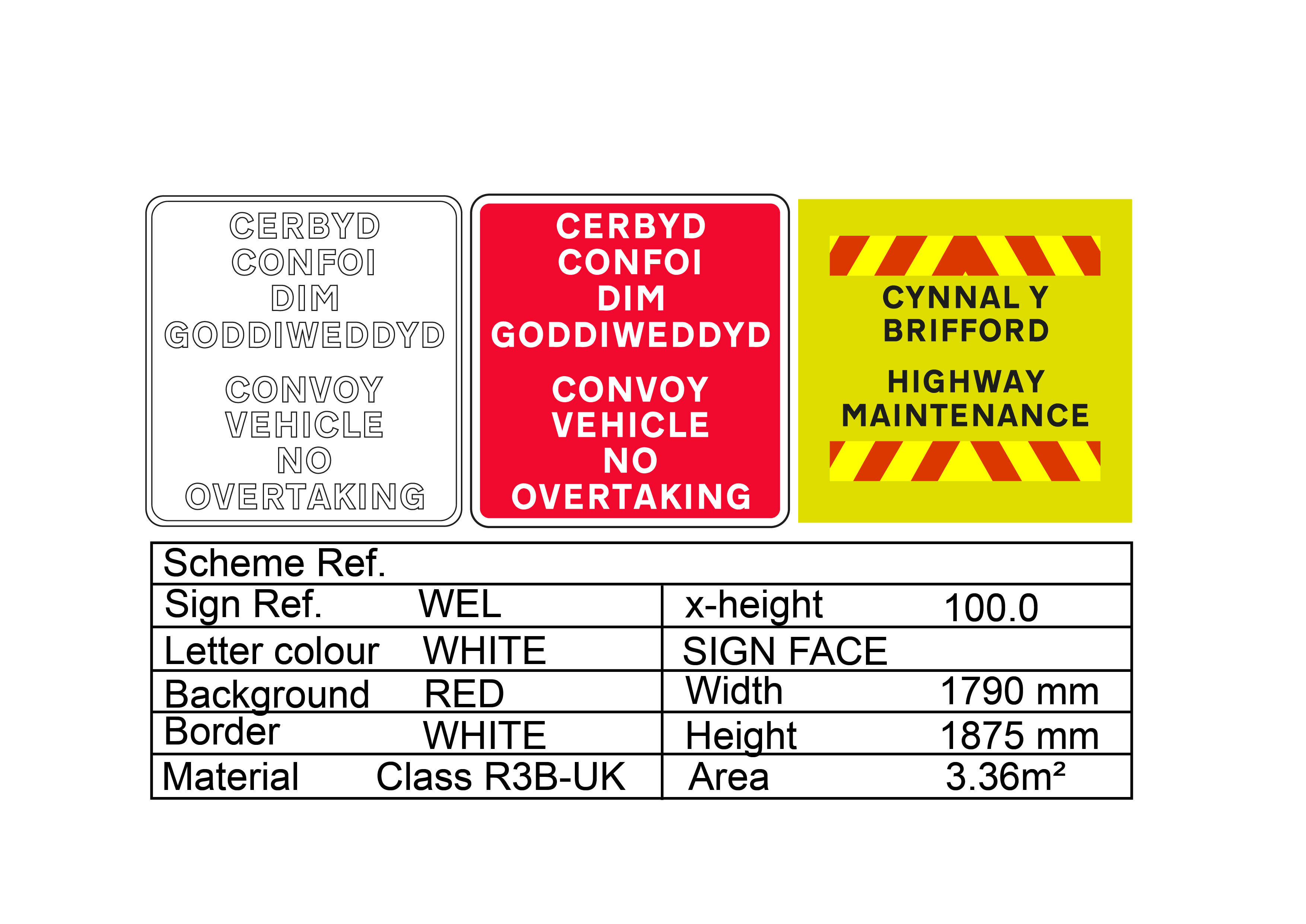
This section contains the signs which have been authorised for use in connection with the EMCC technique on National Highways roads. For bilingual signage in Wales, please refer to the National Application Annex for Wales.
Any use on other roads or any deviation from this authorisation may require the submission of a new proposal and subsequently a new authorisation.
Notes:
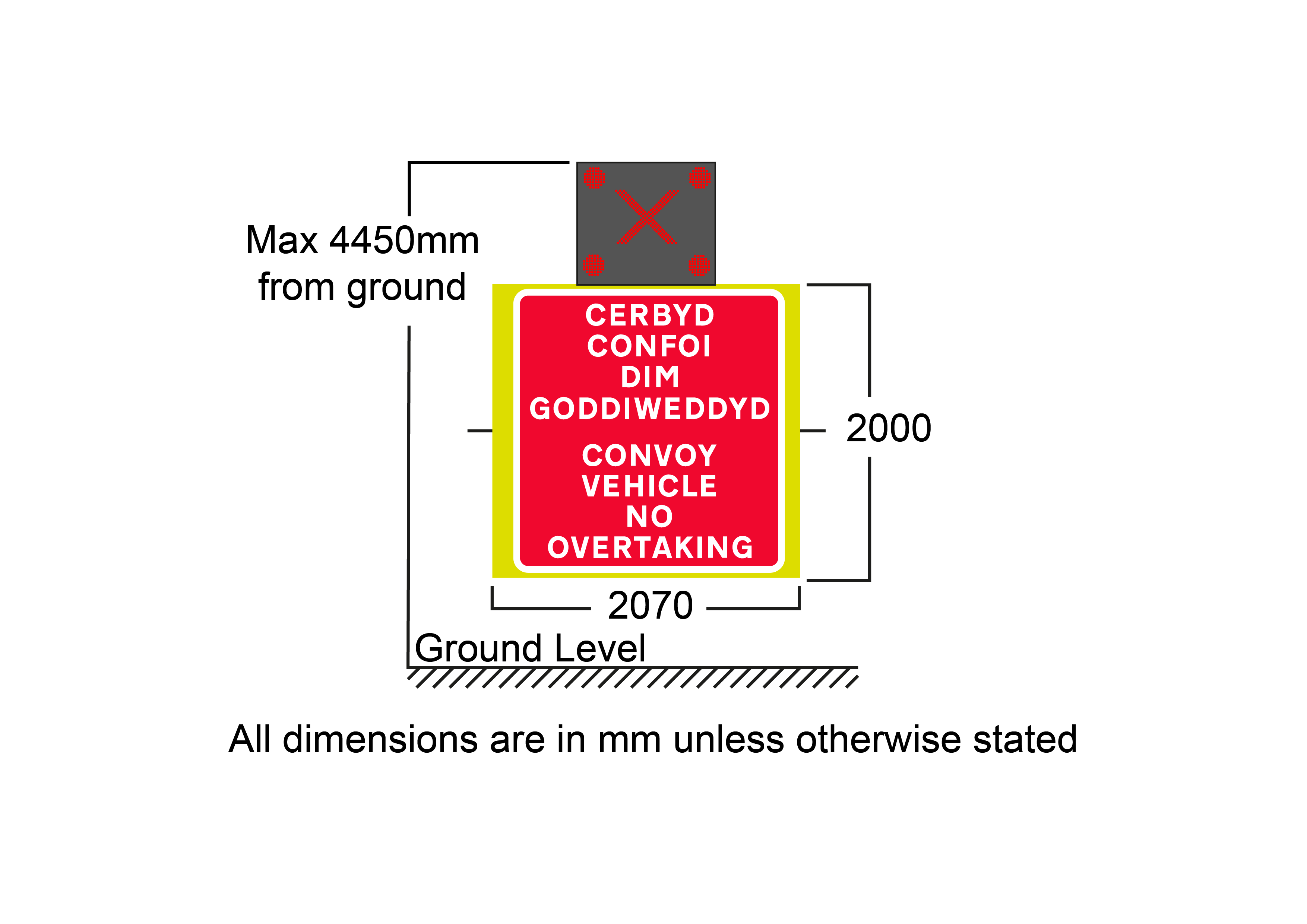
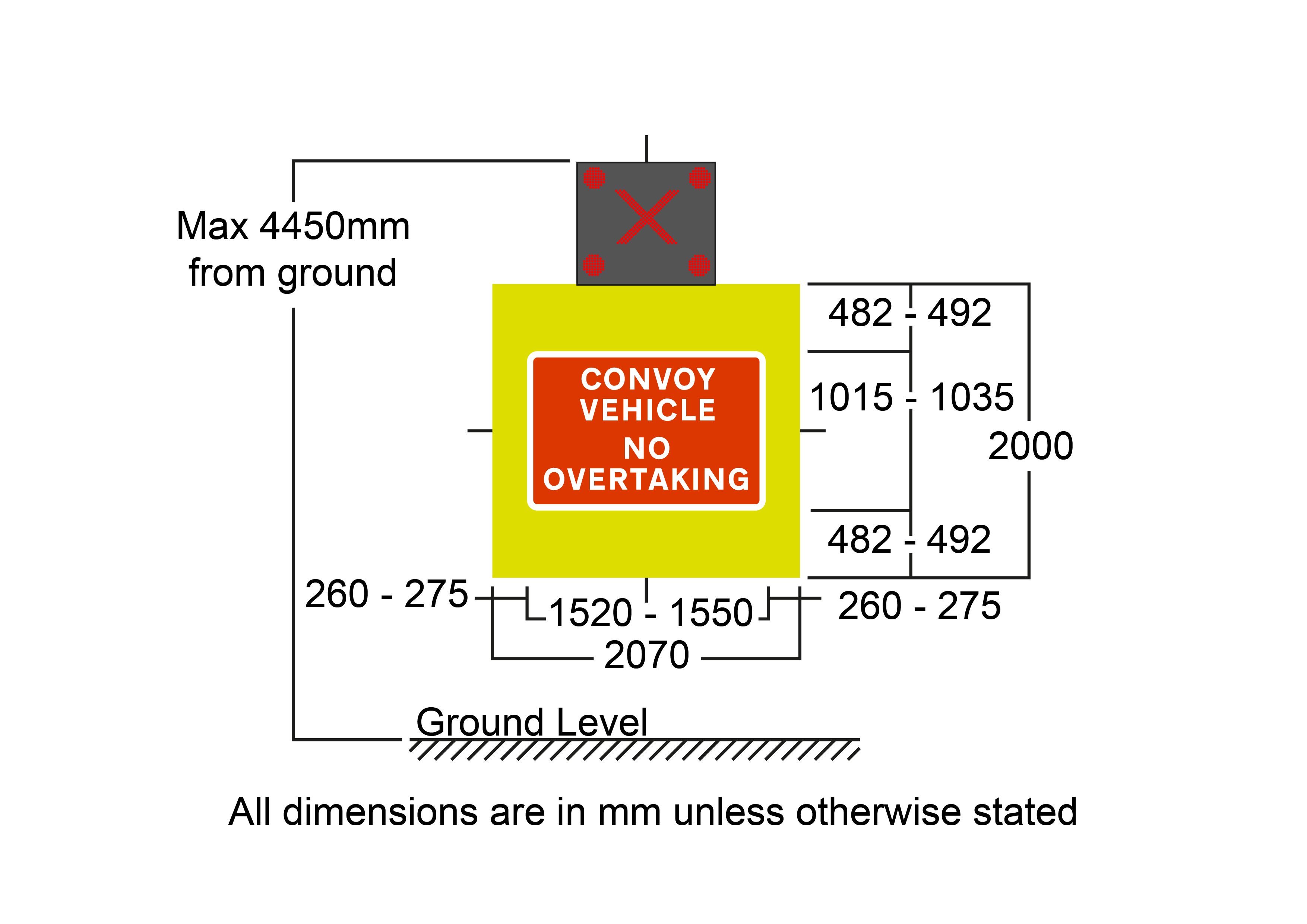
- The authorised sign arrangement is formed of an upper panel, the red 'X’, which currently can only be formed of an LED panel, and a lower panel of the sign to Diagram 7029 “CONVOY VEHICLE NO OVERTAKING” .
- The illumination of the upper panel red 'X’ would need to automatically switch off any warning beacons and lamps in the rear half of the vehicle.
- The sign to Diagram 7029 UKSI 2016/362 (TSRGD) [Ref 7.N] (Schedule 13 Part 6 Item 36) on the lower panel is varied to 100mm x-height. Font, format and form to be as per the working drawing ' Traffic signs images and drawing [Ref 2.I]'. Sign face material to be to BS EN 12899-1 [Ref 1.N]Class R3B UK.
- The yellow backing board is formed of sign face material to a minimum of Class RA2/R2 to BS EN 12899-1 [Ref 1.N] .
- It is essential that the means of switching from this sign to Figure A.9 is done from the operator’s cab. A prism sign was used in the trial vehicle. The roller blind is not prohibited, but there is no known material suitable for a roller blind which meets the above performance classes.
- The option to form a red cross using individual lamps is not currently authorised. The lamp layout shown is indicative, for details of the precise number and layout of lamps refer to any future relevant sign authorisation.
- The lower panel is a standardised arrangement, the dimensions of which it is essential to maintain.
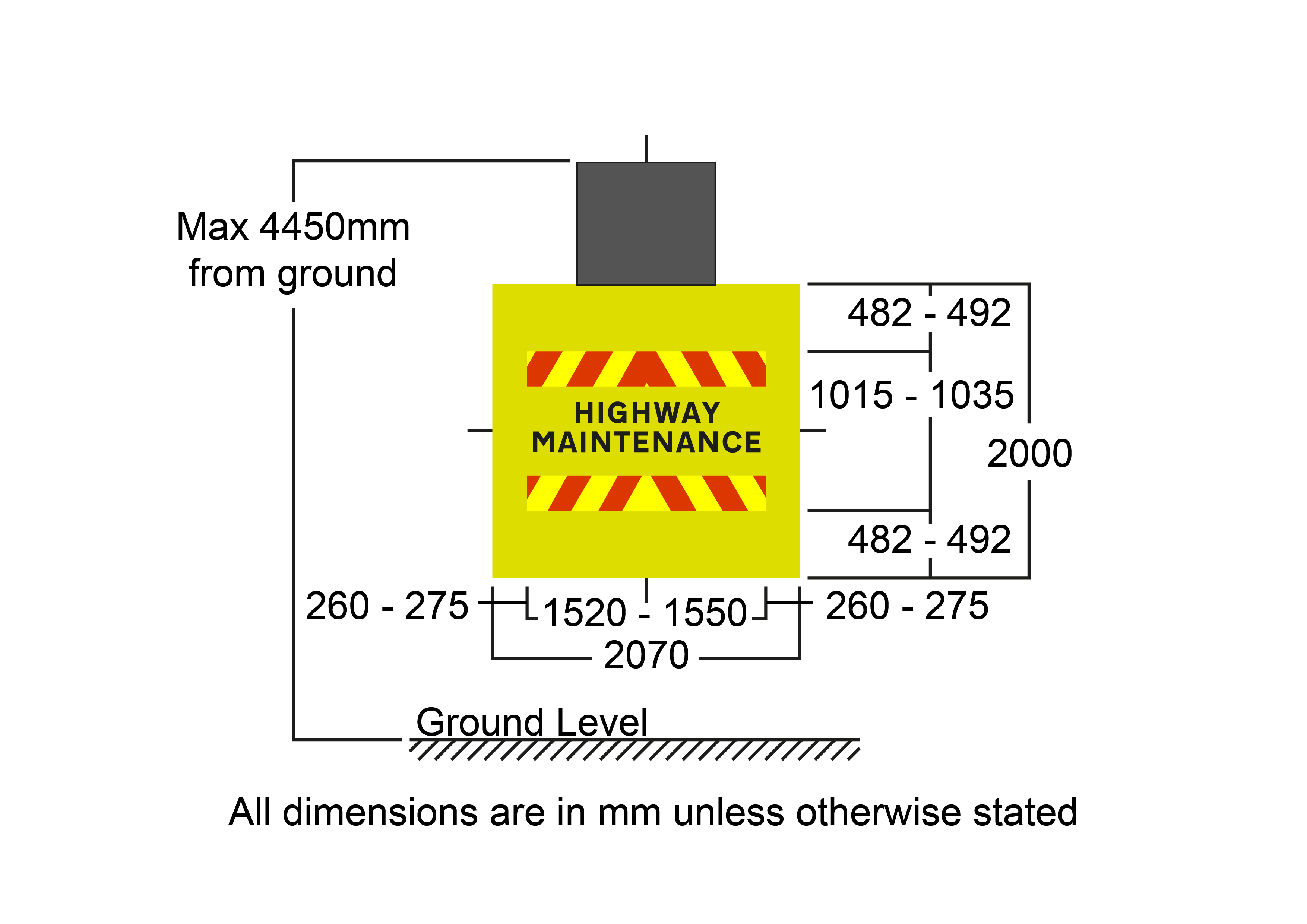
Notes:
- The authorised sign requires the upper panel to be blank or lowered. The lower panel of the sign is required to show Diagram 7404 “HIGHWAY MAINTENANCE” UKSI 2016/362 (TSRGD) [Ref 7.N]with vehicle conspicuity chevrons.
- The sign to Diagram 7404 (Schedule 13 Part 6 Item 12) on the lower panel is varied to 100mm x-height. Font, format and form to be as per the working drawing. Sign face material needs to be to a minimum of class RA2/R2 to BS EN 12899-1 [Ref 1.N].
- The yellow backing board is formed of sign face material to a minimum of Class RA2/R2 to BS EN 12899-1 [Ref 1.N].
- The conspicuity chevrons are formed of red retroreflective material and reflective fluorescent yellow. See TSM Chapter 8 Part 3 Section U4.3 TSM Chapter 8 [Ref 3.I].
- The overall vertical and horizontal size of the chevron and Diagram 7404 combination should be no less than the size of the Diagram 7029 sign.
A6.1 Roadside fixed plate sign used with the technique
The sign arrangement in Figure A.11 was used during the trials in place of the Diagram 7003.1 UKSI 2016/362 (TSRGD) [Ref 7.N] ‘WORKFORCE IN ROAD - SLOW’ sign when the technique was in use.
It is essential that road users are always presented with identical signs when approaching identical situations and therefore the design should not be deviated from. The 150 x-height / 1200mm size sign need to be used on roads with a speed limit of 60 or 70 mph and a smaller 125 x-height / 900 mm sign may be used on roads with an 85th percentile speed of around 50mph.
A yellow or grey backing board may be used with yellow being recommended on wider carriageways.

These signs are indicative and subject to authorisation.
A7 Vehicle and equipment specification
The EMCC vehicle(s) needs to meet the following specification and capability:
- be capable of accelerating to and decelerating from the relevant national speed limit for cars and light vehicles. A 3.5-t van body vehicle normally provides the most suitable arrangement to minimise wind resistance from the rear-mounted equipment and accelerate suitably;
- have a rear-mounted sign arrangement as shown in Figure A.8 and Figure A.9, that can be operated from the cab of the vehicle;
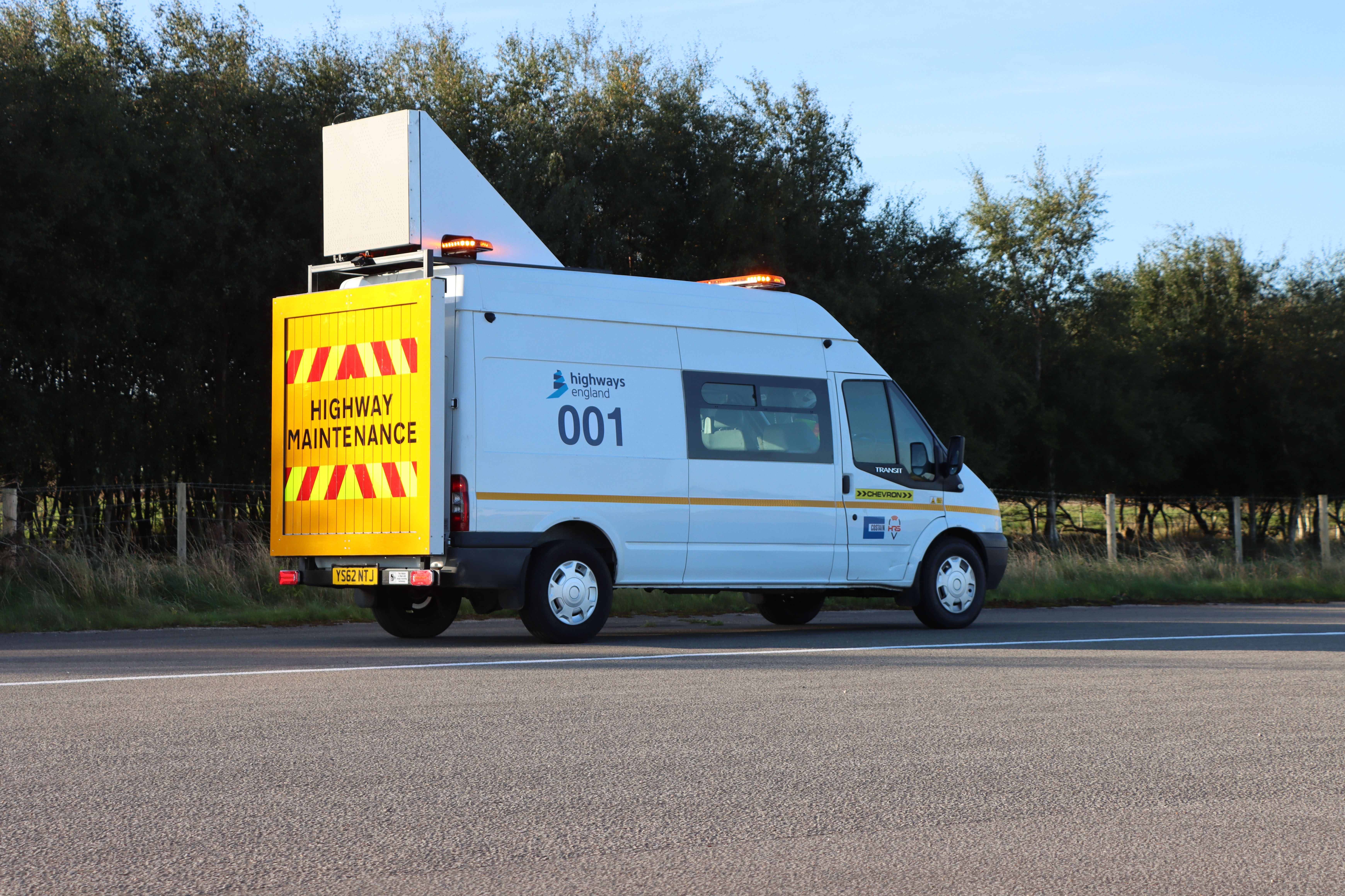
- be of a conspicuous colour and liveried as a highway maintenance vehicle as defined in TSM Chapter 8 [Ref 3.I]. 'Battenburg' livery cannot be used.
- be fitted with a CCTV recording system with front, side and rear cameras sufficient quality to:
-
- view the movement of the vehicle;
- be a reversing aid to the operator;
- to record, retain and retrieve vehicle colour and registration of an incursion for enforcing Authority use at night;
- to capture the front and rear of an incursion as it passes laterally alongside the vehicle; and,
- confirm the display of the authorised aspect shown in Figure A.8 for the enforcing Authority use.
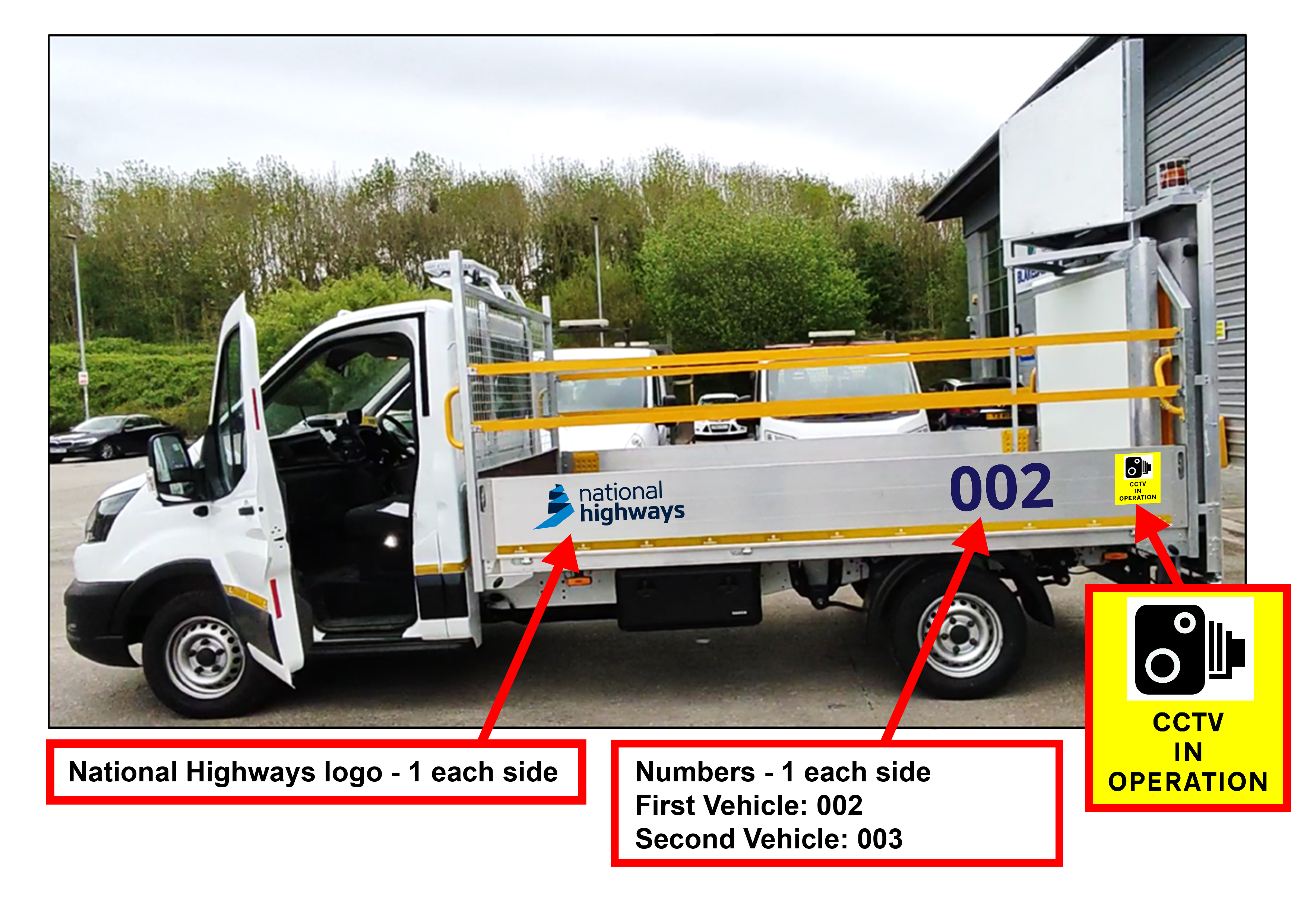
- have CCTV in operation signs, provided on both the sides of the van (see Raising the Bar 27 RtB 27 [Ref 1.I]for a uniform sign;
- be fitted with a cab mounted two-way radio system and charging points for at least two handheld units to be issued to personnel in the working areas;
- be fitted with an automatic digital incursion warning system which can be linked with, and located by, an on-ground incursion warning system, which is able to trigger an approach alert at 500 m and an alarm at 200 m;
- be fitted with a cab-mounted means of manually triggering the incursion alert of the digital incursion warning system to the works operation;
- be fitted with a remotely accessible tracker system recording speed, declaration, acceleration, and geospatial location to review the EMCC speed and manoeuvring, to support and confirm the actions of the EMCC vehicle operator;
- display an agreed logo on each side, normally of the traffic or highway Authority with a unique identification number to the vehicle e.g., “001” in characters of 375 mm character height in Transport Heavy font to enable highway users to identify the EMCC vehicle to the contractor; and,
- display the company or project logo on the driver and passenger doors.
Images of the trial vehicles are provided below and contractors need to maintain uniformity of vehicle presentation to support ongoing road user comprehension and technique safety. The EMCC vehicle may also perform another function such as a welfare van. However, the only staff who are permitted to travel in the vehicle during an EMCC are the trained operator and any one person supporting, assessing, training or supervising the operator.
The signs on the rear of the EMCC vehicle need to be regularly inspected for cleanliness and reflective condition. To ensure the suitability of the signs and vinyl refer to the sign condition assessment guide in TSM Chapter 8 [Ref 3.I].