Design Manual for Roads and Bridges


Drainage
Design
CD 530 Design of soakaways
(formerly HA 118/06)
Version 1.1.0
Summary
This document provides requirements for and advice on the design of soakaways that can be incorporated into systems used to treat and store road runoff prior to discharging to ground.
Application by Overseeing Organisations
Any specific requirements for Overseeing Organisations alternative or supplementary to those given in this document are given in National Application Annexes to this document.
Feedback and Enquiries
Users of this document are encouraged to raise any enquiries and/or provide feedback on the content and usage of this document to the dedicated National Highways team. The email address for all enquiries and feedback is: Standards_Enquiries@highwaysengland.co.uk.
This is a controlled document.Latest release notes
| Document Code | Version number | Date of publication of relevant change | Changes made to | Type of change |
|---|---|---|---|---|
| CD 530 | 1.1.0 | November 2021 | Core document | Incremental change to requirements |
| Minor changes chiefly to clause 3.12. | ||||
Previous versions
| Document Code | Version number | Date of publication of relevant change | Changes made to | Type of change |
|---|---|---|---|---|
| CD 530 | 1 | March 2020 | ||
| CD 530 | 0 | December 2019 |
Foreword
Publishing information
This document is published by National Highways.
This document supersedes HA 118/06 which is withdrawn.
Contractual and legal considerations
This document forms part of the works specification. It does not purport to include all the necessary provisions of a contract. Users are responsible for applying all appropriate documents applicable to their contract.
Introduction
Background
Road runoff can, under certain circumstances, have an adverse effect on receiving waters, including groundwater. This can arise both from the effects of routine runoff and from spillages on the road. Overseeing Organisations have a duty under pollution protection legislation to ensure that road runoff does not pollute receiving waters. Further requirements and advice regarding legislation governing discharges to the ground are provided in LA 113 [Ref 10.N].
The disposal of road runoff through soakaway systems is reasonably well established within the UK. However, pollution attenuation mechanisms affecting road runoff at the discharge point below the soakaway and within the unsaturated zone above the water table have, in the past, been less well understood.
This document originates from a review of available information on the fate and transport of road contaminants and the design of existing road soakaway systems. The review focused primarily on an understanding of the processes operating in the unsaturated zone (i.e. above the water table) and how these may influence soakaway designs and prevent groundwater pollution. This has been backed up by recent research Byrns & Brewin 2010 [Ref 6.I] that identified significant pollution attenuation mechanisms operating within soakaway drainage systems which should be taken into account during soakaway design.
Requirements and advice for the design of other drainage structures such as linear drains are provided in CG 501 [Ref 1.N]. Requirements and advice for the design of infiltration basins and other vegetated systems to treat road runoff are provided in CD 532 [Ref 12.I]. Requirements and advice for the assessment of risks to groundwater from road runoff are provided in LA 113 [Ref 10.N].
This document provides requirements for and advice on the design of soakaways that may be incorporated into systems used to treat and store road runoff prior to discharging to ground. This document is based upon and refers directly to current available design guidance.
Assumptions made in the preparation of this document
The assumptions made in GG 101 [Ref 6.N] apply to this document.
Abbreviations
| Abbreviation | Definition |
|---|---|
| EPA | Environmental protection agency |
| GWDTE | Groundwater dependent terrestrial ecosystems |
Terms and definitions
| Term | Definition |
|---|---|
| Acute impact (pollutants) | Occurs as a result of a severe, usually transient, event. NOTE: For road runoff, acute pollution is usually the result from a spillage of pollutants, but can result from routine runoff |
| Aerobic | In the presence of oxygen (air) |
| Adsorption | The uptake and retention of one substance onto the surface of a another |
| Anaerobic | In the absence of oxygen (air) |
| Chronic impact (pollutants) | The result of ongoing low levels of pollution which can result in the transport and accumulation of sediment-bound pollutants over a longer period of time (months/years) |
| Environmental protection agency/agencies | The relevant national body/bodies responsible for managing the quality of water bodies |
| Exceedance event | A rainfall or flow event that exceeds (that is, is bigger and rarer than) the design event |
| Geocellular tank | A number of geocellular units joined together to form a tank that performs the required design function; for example sub-surface storage |
| Geo-cellular unit | A plastic structure used to form a geocellular tank |
| Infiltration | Herein used as synonymous with percolation – the generally downward flow of water through the unsaturated zone to the water table |
| Permeability | A measure of an aquifer’s capacity to transmit groundwater through a unit metre of its saturated thickness (units in m/day) |
| Saturated zone | That part of an aquifer below the water table in which all connected pore spaces are filled with water |
| Unsaturated zone | The zone between the top of an aquifer (limited above by the ground surface) and the water table (that is, the top of the saturated zone) |
| Volatilisation | Changing of liquid to gaseous phase |
1. Scope
Aspects covered
1.1 This document shall be used for the design of soakaway systems that comprise drainage structures (pits, chambers and trenches) that allow infiltration of road runoff to the ground through their base and sides and that incorporate below-ground storage.
1.2 Soakaway systems shall only be used where space or other site specific constraints prevent the use of a broad and shallow infiltration system.
NOTE 1 Broad and shallow infiltration systems, such as infiltration ponds, offer increased potential for pollution attenuation (see Appendix A) and are the preferred option where the road drainage is to be discharged to ground.
NOTE 2 Other documents provide requirements and advice on the design of alternative infiltration systems that utilise infiltration, such as infiltration ponds in CD 532 [Ref 12.I], grassed channels in CD 521 [Ref 4.N] and reservoir pavements in CD 531 [Ref 9.I].
1.3 Before undertaking the drainage design, an assessment of the flood and pollution risk from highway runoff shall be undertaken in accordance with LA 113 [Ref 10.N].
NOTE 1 The requirements and advice document LA 113 [Ref 10.N] provides an overview of the current knowledge of road runoff in the UK, the ground conditions that are believed to affect its nature, and provides requirements and advice for the assessment of the pollution risk arising from routine road runoff and accidental spillages.
NOTE 2 Methods for assessment of pollution risk and impacts from both routine runoff (chronic impact) and from spillage (acute impact) are provided in LA 113 [Ref 10.N].
1.4 Design proposals for discharging road runoff to the ground, including the selection of the soakaway site, shall be the subject of consultation with the relevant environmental protection agency (EPA).
1.5 The design shall incorporate measures to address constraints identified by the EPA.
NOTE Although under UK legislation consents are not required for the discharge of road runoff, the EPA has the power to serve prohibition notices in respect of discharges that are in breach of pollution legislation.
1.6 The design of the soakaway system shall be based upon site-specific conditions.
NOTE The design of soakaways cannot be prescribed. Each site-specific situation is evaluated individually as there are many factors that will influence soakaway design. These include, for examples: available space; depth of unsaturated zone; geology; discharge rate and volume; and traffic flows.
Implementation
1.7 This document shall be implemented forthwith on all schemes involving the design of soakaways on the Overseeing Organisations’ motorway and all-purpose trunk roads according to the implementation requirements of GG 101 [Ref 6.N].
Use of GG 101
1.8 The requirements contained in GG 101 [Ref 6.N] shall be followed in respect of activities covered by this document.
2. Description of soakaway systems
General
2.1 The design of the soakaway shall promote efficient hydraulic contact between the drainage system and the underlying ground in order to provide effective drainage.
2.2 The primary discharge from the soakaway shall be via infiltration to the sub-surface.
NOTE 1 There are a range of other drainage systems where the primary discharge is to the sub-surface, these include: combined surface and groundwater filter drains; fin drains; filter drains; informal drains or ‘over the edge drainage’. There can be other drainage systems from which discharge to ground occurs but is incidental to the overall function of the drainage (e.g. unlined ditches). Requirements and advice for all these drainage systems is provided in CG 501 [Ref 1.N].
NOTE 2 Surface water drainage features can also incorporate discharges to the sub-surface for example: retention ponds; sedimentation ponds; infiltration basins and wetlands. Requirements and advice for these systems is provided in CD 532 [Ref 12.I].
NOTE 3 Similarly, swales and grassed channels can incorporate discharge to the ground. Requirements and advice for these systems is provided in CD 532 [Ref 12.I].
2.3 Soakaways shall be sited in porous and permeable ground of sufficient depth and lateral extent to be able to accommodate potential maximum discharges under design storm conditions.
2.3.1 Where slow infiltration rates occur, the use of balancing ponds or other flow attenuation mechanisms may be required to accept the quantity of runoff generated under peak flow conditions by the road drainage.
NOTE What is good for the physical disposal of road drainage (that is, rapid dispersal of flow) is the opposite of what is required with respect to the in-ground attenuation of pollutants. Slow infiltration rates can be utilised to optimise these in-ground attenuation processes.
2.4 Soakaway design shall allow for pollution attenuation processes active within the unsaturated zone.
NOTE 1 Pollution attenuation processes can be enhanced by maximising contact with strata with the greatest attenuation potential or preventing direct discharge into strata that do not offer any potential. Further advice is available in LA 113 [Ref 10.N] and CIRIA C753 [Ref 13.N].
NOTE 2 Appendix A provides information on the pollution attenuation processes active in the unsaturated zone which can be taken into account in soakaway design.
2.5 The depth of the unsaturated zone beneath the soakaway shall be maximised.
NOTE The effectiveness of natural attenuation processes can be enhanced through increased depths of unsaturated zone beneath the soakaway.
2.6 The depth from the base of the soakaway to the maximum likely groundwater level shall be a minimum of 1.2 m.
NOTE 1 In accordance with CIRIA C753 [Ref 13.N], adopting a minimum (1 m) depth to groundwater minimises the risk of loss of storage in the soakaway from rising groundwater, reduces the potential for direct discharge into groundwater and reduces the risk of groundwater contamination.
NOTE 2 The Environment Agency sets out a series of position statements with respect to the protection of groundwater: LIT 7660 2018 [Ref 11.I]. Within this document, Section G refers to discharges of sewage effluent into the ground, which in turn refers to BS 6297 2007 [Ref 4.I] that sets a minimum depth of 1.2 m between the base of an infiltration trench and the seasonally highest groundwater level. This minimum depth to groundwater is adopted within this requirement.
2.7 Site specific information shall be gathered to determine the depth to groundwater beneath the base of the soakaway.
2.7.1 To determine the maximum level of groundwater, information may be gathered by adopting a lines of evidence approach.
NOTE 1 The lines of evidence approach can include, for example, site-specific ground investigations and desk studies undertaken by a groundwater specialist.
NOTE 2 Depth to groundwater is variable and seasonal. Short term monitoring alone can be insufficient to determine a representative maximum groundwater level. All available evidence is used to determine this maximum level.
2.8 The design of soakaways, their location and functionality shall incorporate measures to minimise or mitigate potential impacts on landscape and ecology.
NOTE Discharges to groundwater can potentially affect biodiversity (such as down gradient groundwater-dependent terrestrial ecosystems (GWDTE)) through impacts arising from changes in groundwater flow and/or groundwater quality). Impacts on GWDTE can in turn have impacts on landscape. These impacts can be identified through the risk assessment process carried out under LA 113 [Ref 10.N] and mitigation measures incorporated into the design. Open, rubble-filled pits could have direct impacts on biodiversity and landscape.
Soakaway types
Soakaway pits and chambers
2.9 Soakaway chambers shall be formed by excavation of a pit to the required depth.
2.10 The base of the excavation for the soakaway chamber shall be fitted with a concrete footing.
2.11 The sides of the soakaway chamber shall be lined.
2.11.1 The lining of the soakaway chamber may comprise cast in situ segmental concrete, or precast perforated concrete rings or slabs.
NOTE 1 Brickwork or blockwork can be used to line soakaway chambers, but it is unlikely to be suitable for larger soakaways used on motorway and all-purpose trunk roads.
NOTE 2 A typical design for a soakaway chamber utilising precast concrete rings is provided in CIRIA C753 [Ref 13.N].
2.12 The concrete footing and chamber lining shall be porous to permit the outward discharge of water.
2.13 The areas between the sides of the excavation and the chamber lining shall be backfilled with aggregate or other suitable material.
NOTE Based on guidance provided in CIRIA C753 [Ref 13.N] the backfill can comprise, for example,Type B filter material identified in MCHW Series 0500 [Ref 8.N] or selected granular material in accordance with Class 6H of Table 6/1 of MCHW Series 0600 [Ref 9.N].
2.14 The soakaway chamber shall include a cover and inspection hatches in accordance with CD 534 [Ref 2.I] and MCHW Series 0500 [Ref 8.N].
2.15 Unlined pit soakaways shall be filled to the surface with well graded granular material, free of fines, in accordance with Class 6G of Table 6/1 of MCHW Series 0600 [Ref 9.N].
NOTE 1 The granular material provides support to the pit sides to prevent collapse as well as ensuring there is no void which could form a significant safety hazard.
NOTE 2 Fill materials used in pit type soakaways typically have porosity values in the range 20-40%. The porosity of the fill material needs to be known for the hydraulic design calculations in accordance with BRE DG 365 [Ref 11.N]
2.16 Granular materials used for backfill and for unlined pits shall exclude constituents that could result in leaching of harmful substances into the underlying groundwater.
2.17 Filled pits and chambers shall include an inspection well.
NOTE Guidance in BS EN 752 [Ref 5.I] suggests the use of a 225 mm perforated pipe as an inspection well in filled soakaways.
Soakaway trenches
2.18 The design of trench type soakaways shall include inspection tubes (observation wells) at regular intervals.
NOTE Figure 2.18N illustrates the placement of observation wells at intervals along the soakaway trench.
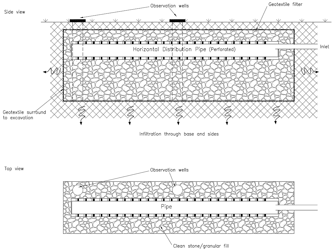
2.19 The design of a trench type soakaway shall allow for inspection tubes (observation wells) to be connected by a horizontal perforated or porous distributor pipe laid along the trench in the top of the granular fill.
2.20 The extreme ends of the trenches shall be identified by inspection tube covers or access covers.
2.21 The design of a trench type soakaway shall allow the volume between the trench structure and the excavation to be backfilled with granular material.
NOTE Trenches will typically have a horizontal base, though this can be changed to reflect site conditions.
2.22 The width of the trench shall be a minimum of 300 mm.
NOTE Trenches tend to require a lower volume of excavation and granular fill material for a given discharge capacity than a soakaway with a square profile. The narrower and longer the trench, the more efficient it is in terms of outflow performance and construction cost compared to wider and shorter trenches.
Geocellular units
2.23 Where geocelullar units or geocellular tanks are used in place of soakaway chambers or soakaway trenches, soakaways shall be designed in accordance with requirements set out in CIRIA C737 [Ref 12.N].
3. Design of soakaway systems
3.1 The design of the soakaway system must prevent direct discharge into groundwater in accordance with the requirements of the EU Directive 2000/60/EC [Ref 3.N].
NOTE The 2000/60/EC [Ref 3.N] (EU Directive 2000/60/EC) introduced measures to prevent and limit the introduction of pollutants (which can potentially occur in road drainage) into groundwater. Further details of the legislation and its relevance to soakaway system design are provided in LA 113 [Ref 10.N].
3.2 The use of boreholes as part of a soakaway system shall be avoided.
NOTE 1 Soakaway systems that include boreholes or deep shafts can by-pass attenuation within the unsaturated zone and could lead to the direct introduction of road runoff into groundwater, contravening UK legislation.
NOTE 2 Use of boreholes or deep shafts as part of a soakaway system design would require a departure from standards and would only be permitted following the completion of an appropriate groundwater risk assessment and consultation and agreement with the EPA.
Overall requirements
3.3 The hydraulic performance of the soakaway system design shall provide sufficient storage and infiltration capacity to allow drainage of the design storm from the carriageway.
3.4 The soakaway drainage system shall be designed to manage surface water runoff from the 1:10 year storm return period, or greater.
3.5 The soakaway system design shall allow for the effects of climate change on peak rainfall intensity and volume over the lifetime of the development.
NOTE Advice on climate change allowance is provided in CG 501 [Ref 1.N] and CIRIA C737 [Ref 12.N].
3.6 The soakaway design shall incorporate measures necessary to provide spillage and pollution control to protect receiving groundwater.
NOTE The level of pollution prevention and control provided is to be commensurate with the risk to groundwater at each site. Guidance on the risk of pollution from accidental spillages is provided in LA 113 [Ref 10.N].
3.7 The soakaway and its associated elements shall adopt a design sympathetic to the local landscape.
NOTE 1 Landscaping requirements and advice can be found in LA 107 [Ref 7.N] and LD 117 [Ref 7.I].
NOTE 2 Whilst the soakaway itself can have little manifestation at the surface the associated elements such as fencing, maintenance facilities, access routes and signage can all have landscape impacts.
Site-specific factors - general site selection
3.8 General site selection shall include assessment of the following factors:
- the hydrogeological potential of the site (that is, is the substrate designated as an aquifer?);
- location of source protection zones (SPZs);
- the minimum depth to groundwater, (that is the minimum thickness of unsaturated zone);
- the soil and rock type and thickness;
- climate (rainfall, evaporation); and,
- the potential for mobilising contaminants (that might already be present in the ground).
NOTE The 2000/60/EC [Ref 3.N] is such that it essentially treats all groundwater with equal weight – i.e. a certain ‘minimum level’ of protection is required. The discharge of non-hazardous substances to groundwater is permitted with adequate risk assessment. Where source protection zones could be impacted, this will affect the level of permissible risk and additional protection can be warranted with respect to the protection of human health. Further advice can be found in LA 113 [Ref 10.N].
3.9 Evaluation of the geological setting of the site and the groundwater risk assessment process described in LA 113 [Ref 10.N] shall be fundamental to the development of the design.
NOTE Further Information on variations in ground conditions and their influence on design is provided in Appendix B.
Site-specific design
3.10 Following general site selection, the site-specific design process shall be followed.
3.11 Soakaway design along the selected route shall allow for variations in ground conditions and the range of factors described in CG 501 [Ref 1.N].
NOTE 1 In the past, designs have tended to be generic for a whole scheme with no variations to take into account differences in ground conditions along the route. As a road generally traverses a wide range of ground conditions, the design needs of the discharge system will change to reflect this.
NOTE 2 Changes along the route could be such that in low lying areas near rivers there could be little unsaturated zone available and a soakaway broad and flat in configuration can be used (or a soakaway not used at all); on high ground, the depth of unsaturated zone can be large enough for smaller deeper structures, reducing the amount of land take.
3.12 The design of the soakaway shall be selected such that:
- the soakaway design suits the site dimensions;
- the road sub-base remains unsaturated when the soakaway is at its maximum design capacity;
- the vertical distance between the base of a soakaway and the groundwater is maximised;
- the soakaway avoids leading to harmful groundwater emergence down gradient;
- the soakaway avoids the surcharge of groundwater leading to harmful water logging or exacerbate groundwater flooding;
- the soakaway avoids leading to the washing out of fines or harmful dissolution of the sub-surface or other instability of the sub-surface, subsidence or heave;
- the soakaway avoids discharge into areas of known landslip hazard; and,
- the soakaway avoids discharges into mine workings (old or current), tunnels, basements, sewers or other sub-surface structures.
3.13 The proximity of buildings to the soakaway site shall be evaluated on a site-specific basis, particularly with respect to ground conditions.
NOTE High discharge volumes and rates can be generated by road run-off. Prescribed limits with respect to the proximity of buildings are not always appropriate to a specific site.
3.14 A minimum of 5 m shall be allowed between the soakaway and any buildings or similar structures.
NOTE 1 BS EN 752 [Ref 5.I] no longer provides for a minimum displacement between a building and a soakaway, but identifies specific risks associated with below-ground infiltration systems that concentrate significant volumes of water in a small area (such as soakaways) and recommends obtaining specialist advice.
NOTE 2 BRE DG 365 [Ref 11.N] recommends that soakaways are constructed at least 5 m from building foundations.
NOTE 3 Both Building Regs Doc. H [Ref 1.I] and the Technical Handbook of SBS TH2017 [Ref 10.I] provide a recommendation that soakaways are a minimum of 5 m from buildings.
Soakaway design
3.15 The soakaway design shall include the following elements:
- capacity to accommodate the quantity of design runoff;
- drainage paths/ports to allow water to infiltrate into surrounding ground;
- filter or settlement mechanisms to prevent the blockage of drains or siltation of the drainage paths and the surrounding ground; and,
- the provision of observation wells/pipes (inspection tubes/chambers) to allow inspection and maintenance.
3.16 The design shall include allowance (outlets and/or overflows) for the controlled overflow of exceedance events.
3.17 Any discharge from overflows for exceedance events shall be routed safely to avoid flooding the road and minimise impact upon adjacent land.
3.18 The drainage system as a whole shall be assessed for the consequences of exceedance for storm return periods in excess of 1 in 100 years in accordance with CG 501 [Ref 1.N] and LA 113 [Ref 10.N].
Unsaturated zone depth and aspect ratio
3.19 The depth and size of soakaways shall be adjusted to allow for variations in depth to groundwater.
NOTE 1 It is good practice to maximise the depth of unsaturated zone below a soakaway device to allow the maximum attenuation of pollutants to occur. On this basis, design depths of no more than 3 to 4 m provide the optimum opportunity for these attenuation processes to occur.
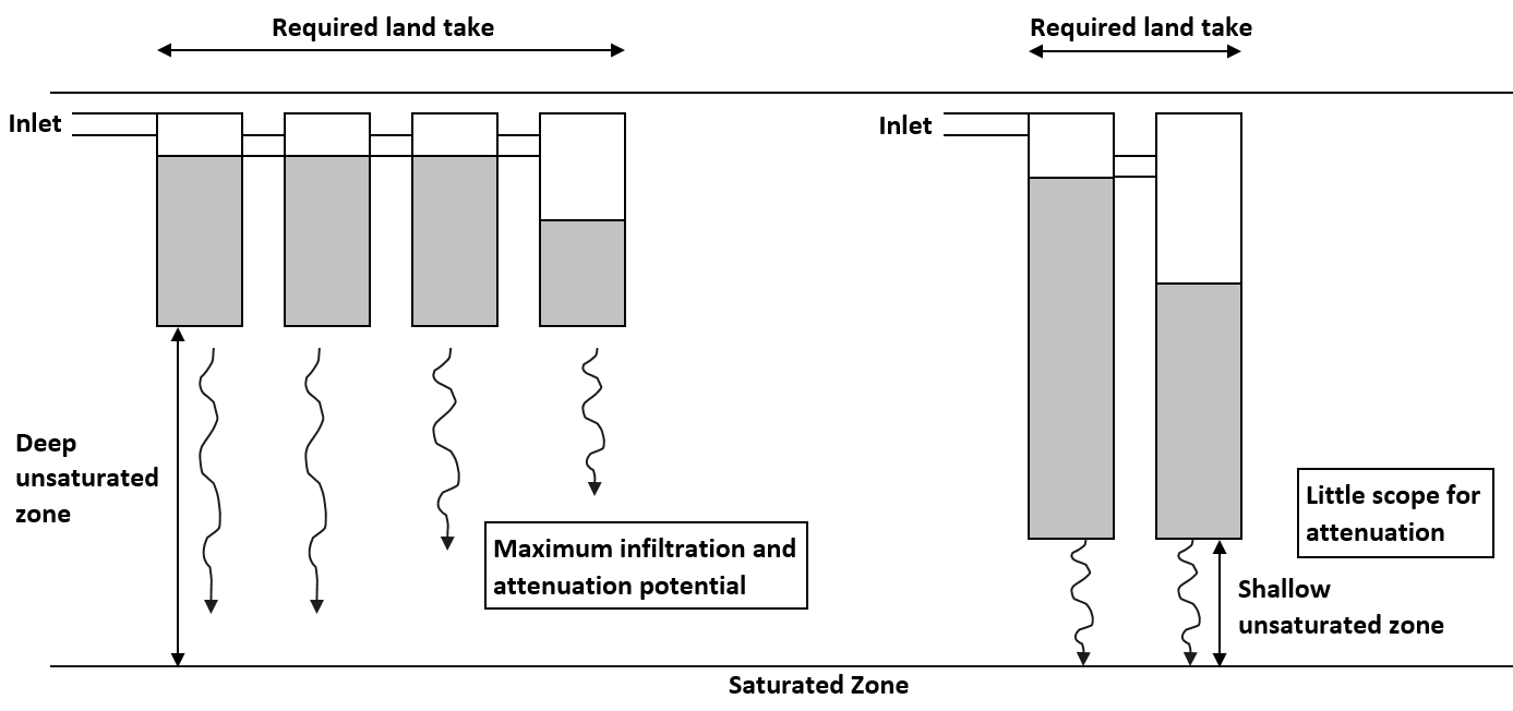
NOTE 2 In areas with less unsaturated depth, the soakaway system can comprise a number of shallow interconnected chambers to provide sufficient short-term storage, whilst maximising the depth of unsaturated zone beneath the soakaway. In areas with a deeper unsaturated zone, the soakaway can comprise fewer deeper chambers, so requiring less land, whilst still maintaining sufficient attenuation capacity. This is illustrated schematically in Figure 3.19N2. Further land can still be needed for access and maintenance.
NOTE 3 Surface infiltration systems (as examples lagoons, and infiltration ponds) also depend on surface area to provide sufficient drainage capacity, so that a large shallow infiltration pond will allow rapid dispersal of water through the semi-permeable base whereas a deep narrow pond will retain water for much longer. Further details on the design of these shallow systems is provided in CD 532 [Ref 12.I].
Storage
3.20 The design of the soakaway drainage system shall provide a balance between sufficient infiltration rate and storage capacity to allow the fast and efficient removal of water from the surface of the road.
3.21 The cumulative storage capacity of the soakaway drainage system shall include storage within the soakaway itself and any additional upstream storage.
NOTE Storage is essential where the discharge rate from the road exceeds the infiltration capacity of the soakaway and provides temporary storage until the generated volume of stormwater is dissipated. Upstream storage can include, for example, detention ponds, oversized pipes, underground chambers or other means.
3.22 The storage capacity within the soakaway system shall be designed to manage peak runoff and rainfall volume from the defined design storm events.
NOTE Guidance in CIRIA C753 [Ref 13.N] suggests that the infiltration component discharges from full to half full within 24 hours so that subsequent rainfall events can be managed. This capacity can be built into system storage upstream of the soakaway (such as in ponds or oversized pipes) and can be included in design calculations.
3.23 The rate of runoff from the road surface shall be calculated with an appropriate design methodology / drainage modelling programme using the actual design rainfall values.
3.24 The modelled outflows from the drainage system shall be utilised in the design of the soakaway system.
NOTE To ensure that a soakaway is designed to suit the actual road or section under consideration, the modelled / calculated result can be used instead of following the methods given in the published design guidance BRE DG 365 [Ref 11.N] and CIRIA R156 [Ref 5.N]).
Spillage and pollution control
3.25 Containment and control measures for potential pollution from accidental spillage shall be provided upstream of the soakaway where the risk assessment carried out in accordance with LA 113 [Ref 10.N] identifies these measures as necessary.
NOTE Containment and control measures will enable spillages to be intercepted before reaching the soakaway or infiltration zone, providing sufficient time for emergency spill responses to be implemented. Guidance on the necessity for the provision of spillage control and containment is provided in LA 113 [Ref 10.N].
3.26 Pre-treatment to remove non-soluble and particulate contaminants (chronic pollutants) shall be provided where the risk assessment carried out in accordance with LA 113 [Ref 10.N] identifies these measures as necessary.
NOTE The risk to receiving groundwater from chronic pollutants can also take into account the potential pollution attenuation capacity of the unsaturated zone.
Design procedures
3.27 The design of soakaways and infiltration trenches shall be undertaken in accordance with either BRE DG 365 [Ref 11.N] or CIRIA R156 [Ref 5.N].
3.27.1 The design procedures in either BRE DG 365 [Ref 11.N] or CIRIA R156 [Ref 5.N] may be selected based on the proposed soakaway design.
NOTE 1 The methodology in BRE DG 365 [Ref 11.N] and CIRIA R156 [Ref 5.N] are similar, but there are important differences between the methods. These are further described in Appendix C.
NOTE 2 The infiltration capacity of a given lithology can be determined by applying either a falling or rising head test via a groundwater monitoring standpipe or borehole. A procedure for undertaking falling and rising head tests is provided in BS 5930 [Ref 3.I]. These tests can potentially be useful at initial design stages as many road schemes will have borehole coverage along the length of the proposed route and initial calculations of the aquifer permeability can be made at each location.
4. Design for construction and maintenance
General guidelines
4.1 Soakaway design shall incorporate measures to intercept sediments before they discharge into the soakaway.
4.1.1 Sediment traps, vortex separators or similar sediment treatment devices may be placed upstream of the soakaway.
4.1.2 Vegetative systems and ponds may be used to intercept sediments upstream of the soakaway.
NOTE 1 The long-term performance of a soakaway depends on maintaining the initial storage volume by keeping the pores clear within the granular fill and by removing any material that is likely to clog the pores of the drainage material or seal the interface between the storage and the adjacent soil.
NOTE 2 Advice on treatment methods is provided in CG 501 [Ref 1.N] and specific advice on vortex separators is given in CD 528 [Ref 13.I]. Advice on vegetative treatment systems is given in CD 532 [Ref 12.I].
NOTE 3 Assessment and advice on the need for treatment of pollutants and spillage is provided in LA 113 [Ref 10.N] and advice on sediment transport and deposition is given in CD 523 [Ref 2.N].
4.2 When geotextiles are used, their incorporation shall be specific to the adopted soakaway design.
4.2.1 Geotextiles may be used to:
- separate granular backfill materials from ground material in the walls of excavated pits;
- prevent fines within the soakaway from migrating outward into granular, surround materials hence reducing clogging of those materials; and,
- lay over the top surface of a granular fill to prevent downward ingress of backfill material during and after surface reinstatement.
NOTE Whilst the interception of sediments prior to entry into the soakaway is an essential pre-requisite to good design, some soakaway designs can incorporate the use of geotextiles to prevent the migration of fine materials within the soakaway.
Health and safety
4.3 The design of the soakaway and its immediate infrastructure and surroundings shall provide safe access for both workers and plant.
4.4 The design of the soakaway and its immediate surroundings shall allow access for emergency personnel and equipment to be able to mitigate the effects of a spillage.
4.5 Provision shall be made for all maintenance operations to be carried out without disruption to the safety and free flow of traffic on the adjacent carriageway.
NOTE Ease of access for maintenance is important, not only to encourage regular maintenance, but also for the safety of the maintenance operatives.
Design for maintenance
4.6 The soakaway design shall facilitate safe access for inspection and maintenance, and include access for the management and removal of sediment.
4.7 During design, an initial management plan shall be developed for the entire drainage system that:
- sets out the objectives of the drainage systems (which might include, for example, flow and pollutant attenuation);
- formulates an adaptable programme of maintenance to include cleaning or replacement of clogged materials;
- establishes procedures (including inspection) for observing and monitoring the behaviour of the drainage system;
- plans for regular reviews of the maintenance scheduling, which could lead to increased or decreased frequency of inspections, cleaning etc; and,
- prescribes the various maintenance operations required.
5. Normative references
The following documents, in whole or in part, are normative references for this document and are indispensable for its application. For dated references, only the edition cited applies. For undated references, the latest edition of the referenced document (including any amendments) applies.
| Ref. | Document |
|---|---|
| Ref 1.N | National Highways. CG 501, 'Design of highway drainage systems' |
| Ref 2.N | National Highways. CD 523, 'Determination of pipe roughness and assessment of sediment deposition to aid pipeline design' |
| Ref 3.N | Europa.eu. 2000/60/EC, 'Directive 2000/60/EC of the European Parliament and of the Council of 23 October 2000 establishing a framework for Community action in the field of water policy' |
| Ref 4.N | National Highways. CD 521, 'Hydraulic design of road edge surface water channels and outlets' |
| Ref 5.N | Construction Industries Research and Information Association, London. CIRIA R156 , 'Infiltration Drainage Manual of Good Practice' |
| Ref 6.N | National Highways. GG 101, 'Introduction to the Design Manual for Roads and Bridges' |
| Ref 7.N | National Highways. LA 107, 'Landscape and visual effects' |
| Ref 8.N | Highways England. MCHW Series 0500, 'Manual of Contract Documents for Highway Works, Volume 1 Specification for Highway Works. Series 500 Drainage and service ducts.' |
| Ref 9.N | Highways England. MCHW Series 0600, 'Manual of Contract Documents for Highway Works, Volume 1 Specification for Highway Works. Series 600 Earthworks' |
| Ref 10.N | National Highways. LA 113, 'Road drainage and the water environment' |
| Ref 11.N | Building Research Establishment. S.L. Garvin. BRE DG 365, 'Soakaway Design ' |
| Ref 12.N | Construction Industries Research and Information Association, London. O’Brien AS, Hsu YS, Lile CR, and Pye SW. CIRIA C737, 'Structural and geotechnical design of modular geocellular drainage systems' |
| Ref 13.N | Construction Industries Research and Information Association, London. Woods-Ballard,B, Wilson,S, Udale Clark,H, Illman,S, Scott,T, Ashley,R, Kellagher,R.. CIRIA C753, 'The SuDS Manual' |
6. Informative references
The following documents are informative references for this document and provide supporting information.
| Ref. | Document |
|---|---|
| Ref 1.I | NBS (RIBA Enterprises). HM Government. Building Regs Doc. H, 'Building Regulations Approved Document H. Drainage and Waste Disposal' |
| Ref 2.I | National Highways. CD 534, 'Chamber tops and gully tops for road drainage and services' |
| Ref 3.I | BSI. BS 5930, 'Code of practice for ground investigations' |
| Ref 4.I | BSI. BS 6297, 'Code of practice for the design and installation of drainage fields for use in wastewater treatment' , 2007 |
| Ref 5.I | BSI. BS EN 752, 'Drain and sewer systems outside buildings - sewer system management.' |
| Ref 6.I | Highways Agency. Byrns, G and Brewin, L. . Byrns & Brewin 2010, 'Fate of Highway Contaminants in the Unsaturated Zone – Final Synthesis Report, March 2010' |
| Ref 7.I | National Highways. LD 117, 'Landscape design' |
| Ref 8.I | Research Center for Environmental and Hazardous Substance Management. Khon Kaen University, Thailand. Napier, F; D’Arcy, B et al. Napier, D'Arcy et al 2008, 'Oil and SUDS: managing a priority urban pollutant. 12th International Conference on Integrated Diffuse Pollution Management' |
| Ref 9.I | National Highways. CD 531, 'Reservoir pavements for drainage attenuation' |
| Ref 10.I | Scottish Government. SBS TH2017, 'Scottish Building Standards Technical Handbook 2017 Domestic Environment ' |
| Ref 11.I | The Environment Agency. Environment Agency and DEFRA. LIT 7660, 'The Environment Agency's approach to groundwater protection' , 2018 |
| Ref 12.I | National Highways. CD 532, 'Vegetated drainage systems for highway runoff' |
| Ref 13.I | National Highways. CD 528, 'Vortex separators for use with road drainage systems' |
Appendix A. Contaminant attenuation processes
A1 Contaminant attenuation processes
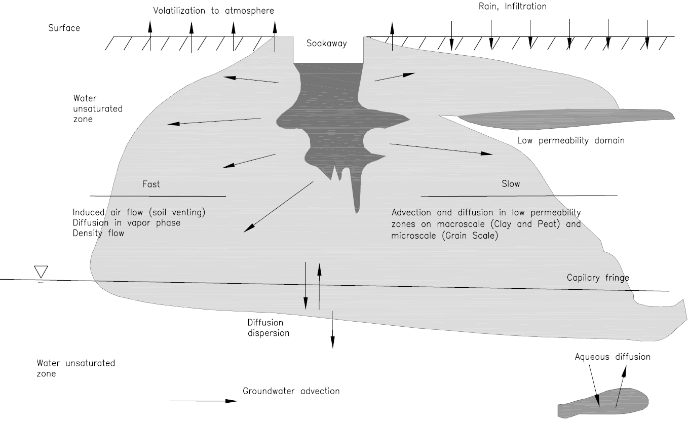
Once they enter the unsaturated zone beneath and around a soakaway, pollutants within road runoff are subject to transport through various pathways, prior to entering groundwater in the saturated zone. These pathways are dependent upon ground conditions and are illustrated generically in Figure A1. Within these pathways, and with the unsaturated zone acting as a substrate, a number of contaminant attenuation processes occur which may act to reduce the concentration of pollutants arriving at the saturated zone.
Natural attenuation results from the combined impacts of physical processes (e.g. filtration), chemical reactions (such as oxidation of sulphides) and biochemical transformations (such as the degradation of compounds under aerobic or anaerobic conditions).
A1.1 Physical attenuation processes
The physical attenuation of contaminants may be by processes associated with adsorption onto the solid matrix through which flow takes place, or by filtration.
Adsorption retains contaminants within the matrix of the unsaturated zone. In general terms, materials of mixed mineralogy, especially those containing a proportion of clay minerals, provide greater opportunity for retention or retardation of particles by adsorption than formations composed principally of silica (such as clean sands and sandstones) or calcium carbonate (clean limestones, particularly the Upper Chalk).
Filtration removes suspended particles, trapping them within the pore spaces of the drainage medium. In general, shallow groundwater, protected by a thin unsaturated zone and composed generally of coarse-grained or heavily fissured materials is likely to be more vulnerable to contamination by particulates (due to lesser potential filtration) than is groundwater in finer grained, more massive materials and with a significant depth of unsaturated zone.
Volatilisation will allow partial attenuation of volatile organic compounds through venting to atmosphere from a porous matrix. The effectiveness of this process depends on the relative temperature of the ground with respect to ambient air and the depth of unsaturated zone.
A1.2 Chemical and biochemical attenuation processes
Chemical and biochemical processes of attenuation act mainly on organic contaminants such as hydrocarbons, although metals may be transformed through processes such as oxidation.
Biodegradation is typically the most important process acting to reduce contaminant mass. The process acts to reduce contamination levels by oxidation-reduction reactions and is dependent on groundwater geochemistry, microbial population, and contaminant properties. Biodegradation can occur under aerobic and or anaerobic conditions and may ultimately result in complete degradation of many organic contaminants.
Abiotic degradation can result in partial or complete degradation of contaminants through chemical transformations. These reactions are dependent on the contaminant properties and groundwater geochemistry. Rates of degradation are typically much slower than those associated with biodegradation.
Research by ( Byrns & Brewin 2010 [Ref 6.I] and Napier, D'Arcy et al 2008 [Ref 8.I]) into the fate of contaminants in the unsaturated zone has highlighted the attenuation potential of organic-rich layers within drainage systems, such as topsoil and other horizons. Field tests have shown significant reductions in contaminant concentrations, both organic and inorganic. This attenuation potential within the unsaturated zone should be considered during the design stages of any soakaway system. Sediments with clay and silt particles provide greater attenuation capacity than coarser sands and gravels due to increased surface area and hence increased sorption potential. Organic matter present within soils can provide suitable environments for soil-borne microbes to provide a degradation mechanism for hydrocarbons.
Organic rich layers should not be by-passed unless it is necessary to provide sufficient drainage capacity and consideration should be made for incorporating soils or other sub-surface strata with high attenuation capacity into the overall soakaway design. On this basis, preferred designs should comprise soakaway systems that are broad and shallow, such as infiltration ponds rather than deep and narrow systems.
Appendix B. Ground conditions and soakaway performance
B1 Infiltration capacity
The performance of a soakaway system will depend to a large extent on the ability of water to infiltrate through the unsaturated zone, which is in turn dependent on the physical properties of the ground and the surface area in contact with the soakaway. The ability of a soakaway to transmit water will be influenced by a number of factors, such as the number and size of drainage ports, the amount of sediment allowed to settle and remain in the chambers, and the degree of choking that occurs immediately outside the chamber in the surrounding ground. For example, special soakaway manhole rings are available from pre-cast concrete suppliers. These have sufficient outlets to allow the water to infiltrate into the ground. If non-standard pre-cast concrete units are used, or a site-specific design for the soakaway chamber is undertaken, then the capacity to discharge into the ground should be considered.
B2 Vertical and horizontal drainage
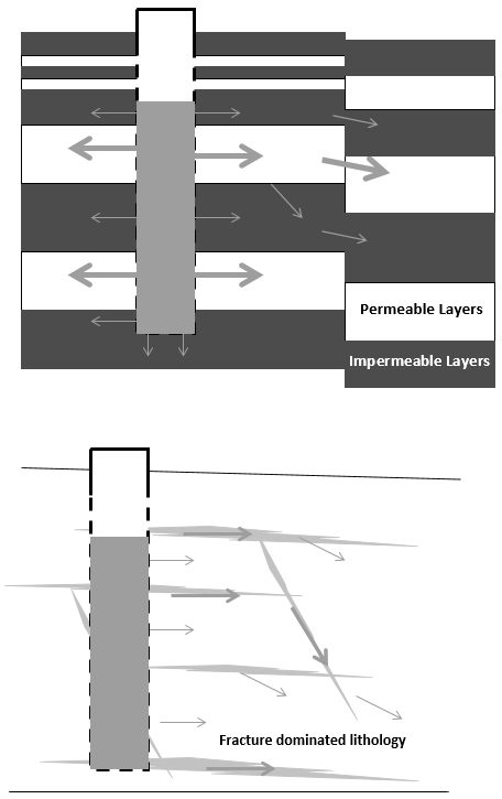
The permeability of a rock formation may vary between the horizontal and vertical, dependent upon the precise lithology and structure. In sedimentary formations consisting of interbedded layers, the horizontal (along bedding) component may be significantly higher than the vertical. The effectiveness of soakaways in layered systems will be heavily influenced by the degree of interconnection between layers of high transmissivity, through fractures and fissures.
In areas of significant fracturing, for example in some sandstones or granite, in an otherwise homogenous lithology, the soakaway performance will be determined largely through interception of one or more fracture systems.
Natural geological systems may be complex, with a variety of flow components contributing to drainage capacity around the soakaway. Figure B.1 shows some possible permutations in drainage characteristics around a soakaway. Site specific information will be required to optimise soakaway design to local flow conditions.
Appendix C. Comparison of design procedures
BRE DG 365 [Ref 11.N] provides advice on the design of soakaways in urban environments, which, whilst not strictly applicable to roads, does provide methods for determining the size of the soakaway required to deal with anticipated levels of runoff.
The BRE methodology uses only the lower portion of the chamber walls (excluding the base of the soakaway) to calculate the infiltration rate into the ground and hence the required storage capacity Byrns & Brewin 2010 [Ref 6.I]. This calculation assumes the base of the soakaway will clog up with sediment.
The BRE methodology uses a 10-year return period for a 15 minute duration storm to determine the required storm flow capacity. This may not be appropriate for roads design and use of suitable modelling programmes should be considered to supplement results obtained by the method.
Furthermore, the BRE methodology does not allow for attenuation of flow within the drainage system itself. Road drainage systems will very often comprise long drain runs which run to a low point in the road to where the soakaway drainage is provided. A significant amount of water will be attenuated as it flows through the drainage run, effectively reducing the peak flow at the soakaway. The BRE methodology can therefore over design the required soakaway capacity based on inflow volume from the road. In order to accurately calculate the required soakaway size the inflow calculation used in the guidance should be replaced with the design flows calculated for the road based on guidance in CG 501 [Ref 1.N].
CIRIA R156 [Ref 5.N] provides brief guidance on designs of drainage systems for a range of drainage scenarios, including roads. This report provides methods for determining the required size for a drainage system based on the amount of rainfall and infiltration characteristics of the ground.
The methodology within CIRIA R156 [Ref 5.N] uses the lower portion of the chamber walls plus the base of the soakaway to calculate the infiltration rate into the ground and hence the required storage capacity. It should be noted that over time the base of a soakaway can become silted, unless adequate maintenance or upstream protective measures are implemented. Incorporating the base into the contact area can thus lead to overestimating the rate of infiltration and underestimating the volume of storage. This method can therefore underestimate the size of soakaway required for a given inflow runoff rate.
The design guidelines in BRE DG 365 [Ref 11.N] and CIRIA R156 [Ref 5.N] may not always give similar results for a specific circumstance because the two methods treat the factor of safety in different ways.